background image

Establishing Basic Connectivity

Router Identification

The domain name defines the network or subnetwork that the Services Router
belongs to. The hostname refers to the specific machine, while the domain
name is shared among all the devices in a given network. Together the
hostname and domain name identify the router in the network.

Root Password

The root user has complete privileges to configure the Services Router, and
manage files in the router’s file system. Initially, the root password is not defined
on the router. To ensure basic security, you must define the root password
during initial configuration. If a root password is not defined, you cannot
commit configuration settings to take effect on the router.

If you use a plain-text password, the router displays the password as a encrypted
string so that users viewing the configuration cannot easily see the password.

The root password must meet the following conditions:

The password must be at least 6 characters long.

You can include most character classes in a password (alphabetic, numeric,
and special characters), except control characters.

Valid passwords must contain at least one change of case or character class.

For Common Criteria environments only, the password must be between 10 and
20 characters long and must include at least three of the five character classes
(uppercase letters, lowercase letters, punctuation marks, numbers, and other special
characters). Control characters are not recommended. For more information, see
the

Secure Configuration Guide for Common Criteria and JUNOS-FIPS

.

Time Zone and System Time

You define the time zone for the location where you plan to operate
the Services Router by using a designation that consists of the
following information for the location:

Name of the continent or ocean—For example,

America

or

Atlantic

Name of the major city or other geographic feature in the time zone—For
example,

Detroit

or

Azores

A Network Time Protocol (NTP) server provides accurate time across a network.
The router synchronizes the system time with the NTP server, and periodically
accesses the NTP server to maintain the correct time.

The time zone and system time must be accurate so that the router
schedules events and operations as expected.

Basic Connectivity Overview

95

Summary of Contents for J4350

Page 1: ...and J6350 Services Router Getting Started Guide Release 8 1 Juniper Networks Inc 1194 North Mathilda Avenue Sunnyvale California 94089 USA 408 745 2000 www juniper net Part Number 530 016824 01 Revis...

Page 2: ...ise this publication without notice Products made or sold by Juniper Networks or components thereof might be covered by one or more of the following patents that are owned by or licensed to Juniper Ne...

Page 3: ...rise Edition of the Steel Belted Radius software may be used by Customer only to manage access to Customer s enterprise network Specifically service provider customers are expressly prohibited from us...

Page 4: ...shall provide Customer with the interface information needed to achieve interoperability between the Software and another independently created program on payment of applicable fee if any Customer sha...

Page 5: ...hapter 5 Preparing for Router Installation 71 Chapter 6 Installing and Connecting a Services Router 81 Chapter 7 Establishing Basic Connectivity 93 Chapter 8 Configuring Secure Web Access 115 Chapter...

Page 6: ...ng Started Guide Part 4 J series Requirements and Specifications Chapter 13 Network Cable Specifications and Connector Pinouts 185 Chapter 14 Safety and Regulatory Compliance Information 201 Part 5 In...

Page 7: ...s Software Features and Licenses 5 Chapter 2 System Overview 9 J4350 and J6350 Services Router Hardware Features 9 Chassis 9 Midplane 14 Routing Engine 14 Boot Devices 15 Front Panel 15 Physical Inter...

Page 8: ...SHDSL PIM 46 Chapter 4 Services Router User Interface Overview 49 User Interface Overview 49 J Web Overview 49 CLI Overview 50 Comparison of Configuration Interfaces 50 Before You Begin 52 Using the J...

Page 9: ...talling a J4350 and J6350 Services Router 83 Connecting Interface Cables to a Services Router 85 Chassis Grounding 86 Connecting Power 86 Connecting AC Power 86 Connecting DC Power 88 Powering a Servi...

Page 10: ...rvices Router 126 Automatic Configuration of a New Services Router 127 Before You Begin 127 Configuring Autoinstallation with a Configuration Editor 128 Verifying Autoinstallation 129 Verifying Autoin...

Page 11: ...Installing an AC Power Supply in a J6350 Router 161 Replacing a DC Power Supply Cable 162 Removing a DC Power Supply from a J6350 Router 163 Installing a DC Power Supply in a J6350 Router 165 Removing...

Page 12: ...Regulatory Compliance Information 201 Definition of Safety Warning Levels 201 Safety Guidelines and Warnings 203 General Safety Guidelines and Warnings 203 Qualified Personnel Warning 204 Preventing...

Page 13: ...rational Safety Guidelines and Warnings 231 Battery Handling Warning 232 Jewelry Removal Warning 233 Lightning Activity Warning 235 Operating Temperature Warning 236 Product Disposal Warning 238 Agenc...

Page 14: ...J4350 and J6350 Services Router Getting Started Guide xiv Table of Contents...

Page 15: ...outer install licenses and establish basic connectivity NOTE This guide documents Release 8 1 of the JUNOS software For additional information about J series Services Routers either corrections to or...

Page 16: ...lowing audiences Customers with technical knowledge of and experience with networks and the Internet Network administrators who install configure and manage Internet routers but are unfamiliar with th...

Page 17: ...commands files and directories IP addresses configuration hierarchy levels or labels on routing platform components To configure a stub area include the stub statement at the edit protocols ospf area...

Page 18: ...ware manuals listed in Table 4 Table 4 J series Guides and Related JUNOS Software Publications Chapter in a J series Guide Corresponding JUNOS Software Manual Getting Started Guide for Your Router Ser...

Page 19: ...nce Configuring Data Link Switching JUNOS Services Interfaces Configuration Guide JUNOS System Basics and Services Command Reference Policy Framework Overview Configuring Routing Policies JUNOS Policy...

Page 20: ...ng Protocols and Policies Command Reference Configuring Packet Capture JUNOS Services Interfaces Configuration Guide Configuring RPM Probes JUNOS System Basics and Services Command Reference Documenta...

Page 21: ...ies Overview Overview of J4350 and J6350 Services Routers on page 3 System Overview on page 9 Physical Interface Modules Overview on page 27 Services Router User Interface Overview on page 49 J series...

Page 22: ...2 J series Overview...

Page 23: ...ows you to manage your Services Router without using the command line interface CLI The J Web interface provides access to all JUNOS functionality and features The J Web interface also provides Quick...

Page 24: ...net ports with link speeds of 10 100 1000 Mbps over a copper interface and six slots for field replaceable Physical Interface Modules PIMs Two of the six slots slots 3 and 6 support high speed interfa...

Page 25: ...slots slots 2 3 5 and 6 support high speed interfaces ePIMs The J6350 Services Router supports the following field replaceable PIMs SFP Gigabit Ethernet ePIM 1 port Copper Gigabit Ethernet ePIM 1 por...

Page 26: ...s Network Services CLNS End system to Intermediate system ES IS protocol IS IS extensions BGP extensions Static routes Multiprotocol Label Switching MPLS Layer 2 and Layer 3 virtual private networks V...

Page 27: ...forwarding Multilink Frame Relay Encapsulation Multilink PPP Data link switching DLSw License required Policing and shaping Class based queuing with prioritization Weighted random early detection WRE...

Page 28: ...nt through the console Telnet or SSH System Management Simple Network Management Protocol version 1 SNMPv1 and SNMPv2 J Flow flow monitoring and accounting License required for J Flow Packet capture P...

Page 29: ...s J4350 and J6350 Services Router Hardware Features on page 9 Software Overview on page 23 J4350 and J6350 Services Router Hardware Features This section contains the following topics Chassis on page...

Page 30: ...an ESD strap could result in damage to the router The router must be connected to earth ground during normal operation The protective earthing terminals on the rear of the chassis are provided to conn...

Page 31: ...minal NOTE The J4350 AC powered chassis has a power switch and does not include a power supply LED unlike the J6350 AC powered chassis Figure 3 Rear of J6350 AC Powered Chassis g003801 AC power applia...

Page 32: ...DC terminal block Power supply fan exhaust Power supply LED Protective earthing terminal Figure 5 Rear of DC Powered J6350 Chassis g003802 DC terminal block Power supply ejector Protective earthing t...

Page 33: ...nterface Physical Interface Module PIM Module PIM Physical Interface Module PIM g003839 Rear Compact flash drive Fans 3 Crypto Accelerator Module Power supply DRAM Table 6 summarizes the physical spec...

Page 34: ...Routing Engine and from the Routing Engine across the midplane to the destination PIM Routing Engine The Routing Engine provides three main functions Creates the packet forwarding switch fabric for th...

Page 35: ...re of J4350 Services Routers To determine whether there is a Crypto Accelerator Module installed on your router issue the show chassis hardware command Compact flash drive Provides primary storage for...

Page 36: ...e 16 Power Button and POWER LED on page 17 STATUS LED on page 18 ALARM LED on page 18 HA LED on page 19 RESET CONFIG Button on page 19 Built In Gigabit Ethernet Ports on page 19 Console Port on page 2...

Page 37: ...wer button to power the Services Router on and off When you power on the router the Routing Engine boots as the power supply completes its startup sequence The POWER LED is located to the upper left o...

Page 38: ...9 describes the ALARM LED Table 9 ALARM LED Color State Description Red On steadily Major alarm indicates a critical situation on the router that has resulted from one of the following conditions A r...

Page 39: ...gurations and rescue configuration and loads and commits the factory configuration You can change the default behavior of the RESET CONFIG button For more information see the J series Services Router...

Page 40: ...ices Router Administration Guide AUX Port The port labeled AUX on the front panel of the J4350 or J6350 Services Router is for future use and is not activated USB Port The USB ports on the front panel...

Page 41: ...e router to power and ground see Connecting Power on page 86 J6350 Power System The J6350 Services Router uses either AC or DC power You can install one or two autosensing load sharing power supplies...

Page 42: ...s router components within the acceptable temperature range see Figure 9 The speed of the fans is adjusted automatically according to current temperature An air filter protects the air intake opening...

Page 43: ...ernet software runs on the Routing Engine The Routing Engine kernel coordinates communication among the JUNOS software processes and provides a link to the Packet Forwarding Engine With the J Web inte...

Page 44: ...Linking the routing tables maintained by the routing protocol process with the forwarding table maintained by the Routing Engine Coordinating communication with the Packet Forwarding Engine primarily...

Page 45: ...process rpd Defines how routing protocols such as RIP OSPF and BGP operate on the router including selecting routes and maintaining fowarding tables Interface process also called device control proces...

Page 46: ...y For more information see Services Router User Interface Overview on page 49 Other user interfaces for the Services Router interact with the management process through the common API interface These...

Page 47: ...re not hot swappable You must power off the Services Router before removing or inserting a PIM For a complete list of supported PIMs see Table 14 For information about network interfaces see the inter...

Page 48: ...erminal equipment DTE device in this case a Services Router to a digital telephone line data terminal equipment to data communication equipment DTE DCE interface Interface that a Services Router the D...

Page 49: ...6 on a J4350 Services Router or slots 2 3 5 and 6 on a J6350 Services Router floating static route Route with an administrative distance greater than the administrative distance of the dynamically le...

Page 50: ...or the field replaceable PIMs supported on J4350 and J6350 Services Routers NOTE Although J4350 and J6350 Services Routers support PIMs that were introduced before the JUNOS 8 0 release these routers...

Page 51: ...Fast Ethernet JUNOS 8 0 and later Can be installed on any PCI Express slot as follows J4350 Slots 3 and 6 Ports 0 through 3 J6350 Slots 2 3 5 and 6 Ports 0 through 3 fe 3 0 0 4 Port ISDN BRI JUNOS 8 0...

Page 52: ...IMs in slots 3 and 6 J6350 Install up to four Gigabit Ethernet ePIMs in slots 2 3 5 and 6 NOTE High speed slots are labeled with an E on the front panel slot number diagram Figure 10 shows the Copper...

Page 53: ...or multimode optical cable NOTE Configure Gigabit Ethernet interfaces up to a maximum MTU size of 9018 bytes For alarms see the configuring and monitoring alarms information in the J series Services...

Page 54: ...ta communication equipment DCE cables Local and remote loopback diagnostics Configurable clock rate for the transmit Tx clock and receive Rx clock For pinouts of cable connectors for serial PIMs see S...

Page 55: ...1 network media types Each PIM has two physical T1 or E1 ports with an integrated channel service unit CSU or data service unit DSU Figure 13 Dual Port T1 PIM T1 STATUS STATUS PORT 0 PORT 1 g002331 Fi...

Page 56: ...d E1 Ports Color State Description Green On steadily Online with no alarms or failures Red On steadily Active with a local alarm The router has detected a failure Unlit Off Offline Dual Port Channeliz...

Page 57: ...NOTE For a clear channel T1 or E1 interface the maximum MTU is 9150 bytes 56 Kbps and 64 Kbps modes ANSI T1 102 T1 107 and T1 403 standards compliance G 703 G 704 and G 706 E1 standards compliance In...

Page 58: ...arms or failures and the physical layer is active Red Online Port is active with a local alarm The router has detected a failure and the physical layer is inactive Yellow Online Port is online with al...

Page 59: ...3 far end alarm and control FEAC diagnostics For pinouts of cable connectors for T3 and E3 PIMs see E3 and T3 BNC Connector Pinout on page 198 For alarms see the configuring and monitoring alarms info...

Page 60: ...HERNET 10 100 ACTIVITY PORT 1 LINK SPEED g002326 The Dual Port Fast Ethernet PIM provides the following key features Onboard network processor Full duplex and half duplex modes Media access control MA...

Page 61: ...ePIM You can install 4 Port Fast Ethernet ePIMs in any of the high speed slots as follows J4350 Install up to two 4 Port Fast Ethernet ePIMs in slots 3 and 6 J6350 Install up to four 4 Port Fast Ether...

Page 62: ...m frame size of 1514 bytes Jumbo frames are not supported For information about installing and removing a PIM see Replacing a PIM on page 144 Fast Ethernet LEDs indicate link status and activity Table...

Page 63: ...U ISDN BRI PIMs provide the following key features Onboard network processor Bandwidth on demand Dial backup Dial on demand routing backup floating static and dialer watch For pinouts of cable connect...

Page 64: ...ONLINE Unlit Off BRI interface is offline Green On steadily PIM is online and operational Red Disconnected PIM is not operational and needs replacement STATUS Unlit Off PIM is offline ADSL PIM The ADS...

Page 65: ...see the configuring and monitoring alarms information in the J series Services Router Administration Guide For installing and removing a PIM see Replacing a PIM on page 144 The ADSL PIMs have two LED...

Page 66: ...e mode supports autodetection of line rate and fixed line rates from 192 Kbps to 2 304 Mbps in 64 Kbps increments 1 port four wire mode supports fixed line rates from 384 Kbps to 4 608 Mbps in 128 Kbp...

Page 67: ...Table 24 LEDs for G SHDSL PIMs Label Color State Description Green On steadily Online with no alarms or failures Red Disconnected Initialization of the PIM has failed ONLINE Unlit Off PIM is booting...

Page 68: ...J4350 and J6350 Services Router Getting Started Guide 48 Field Replaceable PIMs...

Page 69: ...ge 50 J Web Overview The J Web graphical user interface GUI allows you to monitor configure troubleshoot and manage the Services Router by means of a Web browser with Hypertext Transfer Protocol HTTP...

Page 70: ...ving around on the command line and scrolling through a buffer of recently executed commands The CLI has two modes Operational mode Complete set of commands to control the CLI environment monitor and...

Page 71: ...tion page to configure the Services Router for basic connectivity so you can manage it from the network Configure basic router services Setup Secure access Interfaces User access SNMP notifications Ro...

Page 72: ...f configuration statements Create an ASCII text file that contains the statement hierarchy Upload a complete configuration or roll back to a previous configuration Create or delete a rescue configurat...

Page 73: ...ur Web browser type the hostname or IP address of the Services Router and press Enter The J Web login page appears 3 On the login page type your username and password and click Log In To correct or ch...

Page 74: ...Diagnose or Manage task currently displayed in the main pane Click a suboption to access it in the main pane Bottom pane Displays copyright and trademark information The layout of the panes allows you...

Page 75: ...Services Router User Interface Overview Figure 25 J Web Layout Using the J Web Interface 55...

Page 76: ...J4350 and J6350 Services Router Getting Started Guide Figure 26 J Web Layout Configuration Editor 56 Using the J Web Interface...

Page 77: ...or an event summary Alarms View the alarm summary Main Pane Help icon Displays useful information such as the definition format and valid range of an option when you move the cursor over the question...

Page 78: ...ces Router does not detect any activity through the J Web interface for 15 minutes the session times out and is terminated You must log in again to begin a new session To explicitly terminate a J Web...

Page 79: ...vailable commands Information about available commands is provided at each level of the CLI command hierarchy If you type a question mark at any level you see a list of the available commands along wi...

Page 80: ...configuration information file Perform file operations help Provide help information monitor Show real time debugging information mtrace Trace multicast path from source to receiver ping Ping remote t...

Page 81: ...ivate Remove the inactive tag from a statement annotate Annotate the statement with a comment commit Commit current set of changes copy Copy a statement deactivate Add the inactive tag to a statement...

Page 82: ...ecuted commands Table 27 lists some typical CLI editing tasks and the keystrokes that perform them Table 27 CLI Editing Keystrokes Task Category Action Keyboard Sequence Move the cursor back one chara...

Page 83: ...ions type the partial command followed immediately by a question mark To complete a command or option that you have partially typed press Tab or Spacebar If the partially typed letters uniquely identi...

Page 84: ...rm system level operations user host request Type a question mark in the middle of a command name The CLI lists possible command completions that match the letters you have entered so far then redispl...

Page 85: ...configuration statements For example to display summary information for the OSPF hello interval enter the command help reference ospf hello interval help topic string Displays usage guidelines for con...

Page 86: ...he Services Router Minutes of idle time set cli idle time minutes Your session never times out unless your login class specifies a timeout To enable the timeout feature replace timeout with a value be...

Page 87: ...layed on a line set cli screen width width Variable depends on terminal type To change the number of characters displayed on a line replace width with a value between 0 and 100 000 Your terminal type...

Page 88: ...J4350 and J6350 Services Router Getting Started Guide 68 Using the Command Line Interface...

Page 89: ...age 71 Installing and Connecting a Services Router on page 81 Establishing Basic Connectivity on page 93 Configuring Secure Web Access on page 115 Configuring Autoinstallation on page 125 Installing a...

Page 90: ...70 Installing a Services Router...

Page 91: ...l Site Guidelines The following precautions help you plan an acceptable operating environment for your Services Router and avoid environmentally caused equipment failures For the cooling system to fun...

Page 92: ...ropean Telecommunications Standards Institute http www etsi org The horizontal spacing between the rails in a rack that complies with this standard is usually wider than the router s mounting ears whi...

Page 93: ...ude No performance degradation to 10 000 ft 3048 m Relative humidity Normal operation ensured in relative humidity range of 5 to 90 noncondensing Temperature Normal operation ensured in temperature ra...

Page 94: ...Type ABC chemical fire extinguishers dry chemical fire extinguishers near Juniper Networks equipment The primary ingredient in these fire extinguishers is monoammonium phosphate which is very sticky a...

Page 95: ...l surge suppression and shielding Radio Frequency Interference You can reduce or eliminate the emission of radio frequency interference RFI from your site wiring by using twisted pair cable with a goo...

Page 96: ...ale end of the cord inserts into the appliance inlet on the faceplate of the AC power supply The coupler is type C19 as described by International Electrotechnical Commission IEC standard 60320 The pl...

Page 97: ...onnecting Power on page 86 To replace the AC power cord see Replacing an AC Power Supply Cord on page 159 DC Power Connection and Power Cable Specifications Each DC power supply has a single DC input...

Page 98: ...he router for example by causing a short circuit Each DC power cable 48 VDC and return must be 14 AWG single strand wire cable or as permitted by the local code Each lug attached to the power cables m...

Page 99: ...t in Table 33 summarizes the tasks you need to perform when preparing a site for Services Router installation Table 33 Site Preparation Checklist Item or Task Performed By Date Notes Verify that envir...

Page 100: ...J4350 and J6350 Services Router Getting Started Guide 80 Site Preparation Checklist...

Page 101: ...e 90 Before You Begin Before you begin installation complete the following tasks Read the information in Maintenance and Operational Safety Guidelines and Warnings on page 231 with particular attentio...

Page 102: ...also contains an accessory box and quick start instructions NOTE The router is maximally protected inside the shipping carton Do not unpack it until you are ready to begin installation To unpack the r...

Page 103: ...r can be installed into see Rack Requirements on page 72 WARNING If you are installing multiple routers in one rack install the lowest one first and proceed upward in the rack Install heavier routers...

Page 104: ...ced in center hole 1RU rack unit measurement 3 Lift the router and insert the larger elliptical openings in the mounting brackets onto the partially inserted screws so that the router is hanging from...

Page 105: ...pported on the router see the J series Services Router Basic LAN and WAN Access Configuration Guide 1 Have ready a length of the type of cable used by the interface as specified in Network Cable Speci...

Page 106: ...uter before connecting power you connect the grounding cable to earth ground and then attach the lug on the cable to the chassis grounding point with the screw See Connecting Power on page 86 Connecti...

Page 107: ...in which the router is installed c With a Phillips screwdriver remove the screws and washers from the PEM nuts at the grounding point on the rear of the chassis d Place the grounding lug at the other...

Page 108: ...assis is provided to connect the router to ground For DC cable requirements see DC Power Connection and Power Cable Specifications on page 77 To connect DC power to the router 1 Attach an electrostati...

Page 109: ...terminal studs on each power supply You must ensure that power connections maintain the proper polarity The power source cables might be labeled and to indicate their polarity b Verify that a licensed...

Page 110: ...ER LED lights during startup and remains on steadily when the router is operating normally To power off a Services Router you can shut it down in one of the following ways Graceful shutdown Press and...

Page 111: ...ting a Services Router power button to power the router off the router remains in standby mode and a small amount 5 V and 3 3 V of standby voltage is still available in the chassis Powering a Services...

Page 112: ...J4350 and J6350 Services Router Getting Started Guide 92 Powering a Services Router On and Off...

Page 113: ...w on page 49 If you are setting up many Services Routers autoinstallation can help automate the configuration process For more information about autoinstallation see Configuring Autoinstallation on pa...

Page 114: ...rotocol that provides a reliable way of synchronizing the system time of a router root user A superuser or system administrator who can perform any task in the file system secure shell SSH Protocol th...

Page 115: ...lphabetic numeric and special characters except control characters Valid passwords must contain at least one change of case or character class For Common Criteria environments only the password must b...

Page 116: ...bles Backup Router You can specify a backup router to take over when the routing protocol process of the Services Router is not running usually when the Services Router is booting or if its routing pr...

Page 117: ...1 24 and becomes a DHCP server out the ge 0 0 0 interface NOTE If the ge 0 0 1 interface is being used it is set to 192 168 2 1 24 With the router temporarily acting as a DHCP server you can manually...

Page 118: ...rcepted SSH can be configured so that connections are authenticated by a digital certificate SSH uses public private key technology for both connection and authentication The SSH client software must...

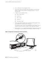
Page 119: ...e provided For a remote connection two dial up modems For a remote modem connection a DB 9 female to DB 25 male adapter or other adapter appropriate for your modem not provided Connecting to a Service...

Page 120: ...t until the STATUS LED on the front panel turns solid green 7 Turn on the power to the management device The router assigns an IP address to the management device within the 192 168 1 0 24 subnetwork...

Page 121: ...shown provided in the router s accessory box plus a DB 9 female to DB 25 male or similar adapter for your modem which you must purchase separately To connect to the CLI using a local management devic...

Page 122: ...that the POWER LED on the front panel turns green The terminal emulation screen on your management device displays the boot sequence When the router has finished booting a login prompt appears 10 Log...

Page 123: ...tible refer to the documentation for your modem and enter equivalent modem commands Before you can connect a dial up modem to the console port on the Services Router you must configure the modem to ac...

Page 124: ...on the router 4 Plug the other end of the Ethernet rollover cable into the RJ 45 to DB 9 serial port adapter supplied with your router 5 Connect the serial port adapter to a separately purchased DB 9...

Page 125: ...before committing any configuration settings Configuring Basic Settings with J Web Quick Configuration J Web Quick Configuration allows you to configure basic settings Figure 25 shows the Quick Confi...

Page 126: ...on Summary Field Function Your Action Identification Host Name required Defines the hostname of the router Type the hostname Domain Name Defines the network or subnetwork that the machine belongs to T...

Page 127: ...e box to the left of the Add button then click Add To delete a domain name click on it in the box above the Add button then click Delete Default Gateway Defines a default gateway through which to dire...

Page 128: ...H RSA public key IP address of the NTP server used to synchronize system time on the Services Router 10 148 2 21 Services Router location Sunnyvale California USA which is in the America Los_Angeles t...

Page 129: ...1 In the J Web interface select Configuration View and Edit Edit Configuration 2 Next to System click Configure or Edit From the edit hierarchy level enter edit system Define the hostname of the rout...

Page 130: ...fine the time zone the router is located in In the Time zone list select the time zone for your router for example America Los_Angeles Set the time zone For example set time zone America Los_Angeles D...

Page 131: ...n the Value box type the name of another domain that the router belongs to for example router net 6 Click OK Set the domains to be searched For example set domain search lab router net set domain sear...

Page 132: ...sting IP address delete lo0 unit 0 family inet address 3 Set the IP address and prefix length of lo0 0 For example set lo0 unit 0 family inet address 172 16 1 24 32 Define the IP address for ge 0 0 0...

Page 133: ...ation View and Edit View Configuration Text Alternatively from configuration mode in the CLI enter the show command The following sample output displays the sample values configured in Table 37 Your o...

Page 134: ...the configuration of basic connectivity Verify that the values displayed are correct for your Services Router For more information about the format of a configuration file see the J series Services R...

Page 135: ...g topics For more information about the J Web interface see the J Web Interface User Guide Secure Web Access Terms on page 115 Secure Web Access Overview on page 116 Before You Begin on page 117 Confi...

Page 136: ...ividual system company or organization In addition to identification data the digital certificate contains a serial number a copy of the certificate holder s public key the identity and digital signat...

Page 137: ...ssl req x509 nodes newkey rsa 1024 keyout filename pem out filename pem Replace filename with the name of a file in which you want the SSL certificate to be written for example new pem 2 When prompted...

Page 138: ...ngs in the J Web interface 1 Generate an SSL certificate An SSL certificate is required for enabling HTTPS or SSL JUNOScript access Skip this step if you are enabling HTTP access For instructions abou...

Page 139: ...and return to the Quick Configuration page click Cancel 5 To verify that Web access is enabled correctly connect to the Services Router using one of the following methods For HTTP access In your Web...

Page 140: ...terfaces at one time To enable HTTP access on all interfaces select the Enable HTTP on All Interfaces check box HTTP Enabled Interfaces Specifies interfaces on which you want to enable HTTP access Sel...

Page 141: ...certificate To enable an SSL certificate select a certificate from the JUNOScript SSL Certificate list for example new Configuring Secure Web Access with a Configuration Editor You can manage your Ser...

Page 142: ...TTPS without specifying an interface HTTPS is enabled on all interfaces 1 On the main Configuration page next to System click Configure or Edit 2 Select the Services check box and click Edit next to i...

Page 143: ...onfiguration For more information about the format of a configuration file see the J series Services Router Basic LAN and WAN Access Configuration Guide Displaying a Secure Access Configuration Purpos...

Page 144: ...J4350 and J6350 Services Router Getting Started Guide 124 Verifying Secure Web Access...

Page 145: ...ion with a Configuration Editor on page 128 Verifying Autoinstallation on page 129 Autoinstallation Terms Before configuring autoinstallation become familiar with the terms defined in Table 41 Table 4...

Page 146: ...level Data Link Control HDLC encapsulation is found on the Services Router autoinstallation attempts to obtain an IP address using DHCP requests bootstrap protocol BOOTP or Reverse Address Resolution...

Page 147: ...ecified boot file Default configuration If the boot file cannot be located or the new Services Router does not receive a specified boot filename from the DHCP server the autoinstallation process then...

Page 148: ...gure the DHCP server to provide a configuration filename to the new Services Router This filename is then used to request a configuration file from a TFTP server Copy the host specific configuration t...

Page 149: ...more Ethernet or serial interfaces to perform autoinstallation and one or two procurement protocols for each interface The router uses the protocols to send a request for an IP address from the interf...

Page 150: ...5 Hostname host ge 000 Hostname source DNS Configuration filename router ge 000 conf Configuration filename server 10 25 100 3 Address acquisition Protocol DHCP Client Acquired address None Protocol R...

Page 151: ...egin on page 132 Managing J series Licenses with the J Web Interface on page 133 Managing J series Licenses with the CLI on page 136 Verifying J series License Management on page 137 J series License...

Page 152: ...sing of BGP routes to internal peers J series Services Router Software License for Advanced Border Router Protocol Support License Key Components A license key consists of two parts License ID Alphanu...

Page 153: ...ing tasks Adding New Licenses with the J Web Interface on page 134 Deleting Licenses with the J Web Interface on page 135 Displaying License Keys with the J Web Interface on page 135 Downloading Licen...

Page 154: ...is determined by the configuration on the router If a feature is configured and the license for that feature is not installed a single license is needed Installed Licenses ID Unique alphanumeric ID o...

Page 155: ...nse Management on page 137 Displaying License Keys with the J Web Interface To display the license keys installed on a Services Router with the J Web license manager 1 In the J Web interface select Ma...

Page 156: ...y from a file or URL enter the following command specifying the filename or the URL where the key is located request system license add filename url To add a license key from the terminal enter the fo...

Page 157: ...7 Verifying J series License Management To verify J series license management perform these tasks Displaying Installed Licenses on page 137 Displaying License Usage on page 138 Displaying Installed Li...

Page 158: ...icense is the expected feature The features enabled are listed by license An all inclusive license has All features listed All configured features have the required licenses installed The Licenses nee...

Page 159: ...nce with license agreements Displaying Installed License Keys Purpose Verify the license keys installed on the Services Router Action From the CLI enter the show system license keys command Sample Out...

Page 160: ...J4350 and J6350 Services Router Getting Started Guide 140 Verifying J series License Management...

Page 161: ...3 Maintaining Services Router Hardware Replacing and Troubleshooting Hardware Components on page 143 Contacting Customer Support and Returning Hardware on page 175 Maintaining Services Router Hardware...

Page 162: ...142 Maintaining Services Router Hardware...

Page 163: ...ns the following topics Replacing Hardware Components on page 143 Troubleshooting Hardware Components on page 171 Replacing Hardware Components This section contains the following topics Tools and Par...

Page 164: ...rnal management device such as a laptop or a terminal server For cable specifications see Network Cable Specifications and Connector Pinouts on page 185 To replace the console port cable 1 Locate an a...

Page 165: ...05 3 Press and release the power button to power off the router Verify that the POWER LED blinks and then turns off 4 Label the cables connected to the PIM so that you can later reconnect each cable t...

Page 166: ...t if the Services Router is disconnected from earth ground For more information about ESD see Preventing Electrostatic Discharge Damage on page 205 2 Press and release the power button to power off th...

Page 167: ...unctioning by issuing the show chassis fpc pic status command described in the JUNOS System Basics and Services Command Reference NOTE In the show chassis fpc pic status command the PIM slot number is...

Page 168: ...ble specifications see Network Cable Specifications and Connector Pinouts on page 185 2 Insert the cable connector into the cable connector port on the PIM faceplate 3 Arrange the cable as necessary t...

Page 169: ...s fpc pic status command described in the JUNOS System Basics and Services Command Reference NOTE In the show chassis fpc pic status command the PIM slot number is reported as an FPC number and the PI...

Page 170: ...f Compact Flash Disk g003842 Compact flash drive On some Services Routers the compact flash is in a horizontal position while on others it is in a vertical position Figure 42 shows the alternative hor...

Page 171: ...ect the strap to the ESD point on the chassis or to an outside ESD point if the router is disconnected from earth ground For more information about ESD see Preventing Electrostatic Discharge Damage on...

Page 172: ...in the horizontal position flat against the bottom of the chassis 7 Slide the compact flash disk out of its slot as shown in Figure 43 Figure 43 Removing the Compact Flash Disk g003835 8 Place the co...

Page 173: ...and release the power button to power on the router Verify that the POWER LED lights steadily after you press the power button Removing and Installing the USB Storage Device USB storage devices are op...

Page 174: ...the strap to the ESD point on the chassis or to an outside ESD point if the router is disconnected from earth ground For more information about ESD see Preventing Electrostatic Discharge Damage on pa...

Page 175: ...the USB storage device upside down and try again 4 To configure the USB storage device with the request system snapshot command see the J series Services Router Administration Guide Removing and Inst...

Page 176: ...y DRAM socket If you are adding a DRAM module to the DRAM configuration proceed directly to Installing a DRAM Module on page 157 To remove a DRAM module 1 Place an electrostatic bag or antistatic mat...

Page 177: ...the module and firmly pull it out of the slot on the Routing Engine 9 Place the DRAM module on the antistatic mat or in the electrostatic bag Figure 46 Adding or Replacing a DRAM Module Remove Instal...

Page 178: ...mly on both ends push the module into the socket until the ejectors click into the closed position see Figure 46 6 Slide the cover onto the chassis 7 Replace and tighten the screws on the sides and to...

Page 179: ...50 Router on page 163 Installing a DC Power Supply in a J6350 Router on page 165 Replacing an AC Power Supply Cord To replace the AC power cord for a redundant power supply 1 Locate a replacement powe...

Page 180: ...ctrostatic discharge ESD grounding strap to your bare wrist and connect the strap to the ESD point on the chassis or to an outside ESD point if the router is disconnected from earth ground For more in...

Page 181: ...cted from earth ground For more information about ESD see Preventing Electrostatic Discharge Damage on page 205 2 Using both hands slide the power supply into the chassis until you feel resistance 3 F...

Page 182: ...ecifications on page 77 CAUTION A licensed electrician must attach a cable lug to the power cable that you supply A cable with an incorrectly attached lug can damage the router for example by causing...

Page 183: ...ntil snug Do not overtighten The screw contains a captive washer used to secure the power cable lug to the terminal block NOTE Each power supply must be connected to a dedicated DC power feed For info...

Page 184: ...maintain the proper polarity The power source cables might be labeled and to indicate their polarity 4 Remove the power cables from the DC power source 5 Use a Phillips screwdriver to remove the clea...

Page 185: ...determines the color coding for the leads on the power cables that attach to the terminal studs on each power supply You must ensure that power connections maintain the proper polarity The power sourc...

Page 186: ...ew secure the negative DC source power cable lug to the 48 VDC terminal Tighten the screw until snug Do not overtighten Apply between 8 lb in 0 9 Nm and 9 lb in 1 02 Nm of torque to the screw NOTE Eac...

Page 187: ...51 shows the location of the Crypto Accelerator Module Figure 51 Crypto Accelerator Module Location g003836 Crypto Accelerator Module To modify a Crypto Accelerator Module configuration use the follow...

Page 188: ...arge Damage on page 205 3 Press and release the power button to power off the Services Router Wait for the POWER LED to turn off 4 Unplug the power cord or cable from the power source receptacle 5 Rem...

Page 189: ...e ESD point on the chassis or to an outside ESD point if the router is disconnected from earth ground For more information about ESD see Preventing Electrostatic Discharge Damage on page 205 b Press a...

Page 190: ...11 Verify that the Crypto Module is correctly installed by issuing the show chassis hardware command as shown in the following example user host show chassis hardware Hardware inventory Item Version...

Page 191: ...tabs on either side of the filter cover 2 Pull the filter cover away from the chassis 3 Remove the old filter 4 Place the new filter in the opening 5 Replace the filter cover by pressing it until it c...

Page 192: ...ternative boot media The Services Router boots from an alternative boot device Typically the router boots from the primary compact flash disk If you configured your router to boot from an alternative...

Page 193: ...er Environmental Tolerances on page 73 Check the air flow See General Site Guidelines on page 71 Check the fans See Cooling System on page 22 If you must replace a fan or the Routing Engine contact JT...

Page 194: ...J4350 and J6350 Services Router Getting Started Guide 174 Troubleshooting Hardware Components...

Page 195: ...number on the router or component To list the router components and their serial numbers enter the following command line interface CLI command user host show chassis hardware Hardware inventory Item...

Page 196: ...Services Routers have two serial number ID labels one on the back of the chassis as shown in Figure 55 and one on the bottom front corner as shown in Figure 56 Figure 55 Location of Serial Number ID L...

Page 197: ...38580 Serial ID label 1 4 5 6 2 3 SLOT NUMBER E E The following sections describe the label location on each type of component PIM Serial Number Label on page 177 J6350 Power Supply Serial Number Labe...

Page 198: ...port from JTAC by telephone be prepared to provide the following information Your existing case number if you have one Details of the failure or problem Type of activity being performed on the router...

Page 199: ...telephone call Part number and serial number of component Your name organization name telephone number and fax number Description of the failure 4 The support representative validates your request and...

Page 200: ...uter software user host request system halt Wait until a message appears on the console confirming that the operating system has halted For more information about the command see the J series Services...

Page 201: ...uately protected with packing materials and packed so that the pieces are prevented from moving around inside the carton Use the original shipping materials if they are available Place individual boar...

Page 202: ...J4350 and J6350 Services Router Getting Started Guide 182 Packing a Router or Component for Shipment...

Page 203: ...J series Requirements and Specifications Network Cable Specifications and Connector Pinouts on page 185 Safety and Regulatory Compliance Information on page 201 J series Requirements and Specificatio...

Page 204: ...184 J series Requirements and Specifications...

Page 205: ...11 Connector Pinout on page 199 ISDN RJ 45 Connector Pinout on page 199 Serial PIM Cable Specifications The 2 port serial PIM uses the cables and connectors summarized in Table 47 Pinouts are detaile...

Page 206: ...M 34 female Standard Normally included with M 34 connector shell 18 Table 55 X 21 DTE DB 15 male M3 threaded jackscrews 13 Table 56 X 21 DCE DB 15 female M3 threaded jacknuts 13 Table 57 RS 232 DTE Ca...

Page 207: ...7 4 Request to Send 48 5 Clear to Send 33 6 Data Set Ready 57 7 Signal Ground 13 8 Data Carrier Detect 56 15 Transmit Clock 52 17 Receive Clock 45 18 Local Loopback 9 20 Data Terminal Ready 5 24 Termi...

Page 208: ...g B 2 24 1 Receive Data B 47 25 48 Request to Send B 6 26 5 Receive Timing B 38 27 37 Clear to Send B 10 29 9 Data Mode B 34 30 33 Terminal Ready B 14 31 13 Receiver Ready B 51 35 52 Terminal Timing B...

Page 209: ...38 25 37 Request to Send B 51 26 52 Receive Timing B 47 27 48 Clear to Send B 34 29 33 Data Mode B 10 30 9 Terminal Ready B 14 31 13 Receiver Ready B 6 35 5 Terminal Timing B 57 37 Send Common 26 to 2...

Page 210: ...cal Loopback 47 19 48 Request to Send B 33 20 Data Terminal Ready A 4 23 Signal Ground 52 24 51 Terminal Timing A 26 to 25 30 to 29 18 to 17 EIA 530A DCE Cable Pinout Table 53 EIA 530A DCE Cable Pinou...

Page 211: ...ady A 4 23 Signal Ground 5 24 6 Terminal Timing A 26 to 25 30 to 29 V 35 DTE Cable Pinout Table 54 V 35 DTE Cable Pinout LFH 60 Pin M 34 Pin LFH 60 Pairing Description 15 A Frame Ground 57 B Signal Gr...

Page 212: ...M 34 Pin LFH 60 Pairing Description 15 A Frame Ground 57 B Signal Ground 37 C Request to Send 48 D Clear to Send 33 E Data Set Ready 13 F Received Line Signal Detector 9 H Data Terminal Ready 45 K Te...

Page 213: ...A 48 3 47 Control A 1 4 2 Receive A 37 5 38 Indicate A 5 6 6 Signal Element Timing A 57 8 Signal Ground 59 9 60 Transmit Data B 47 10 48 Control B 2 11 1 Receive B 38 12 37 Indicate B 6 13 5 Signal E...

Page 214: ...2 48 Indicate B 51 13 52 Signal Element Timing B 30 to 29 RJ 45 Connector Pinout for Fast Ethernet Ports Table 58 describes the RJ 45 connector pinout information NOTE Either a straight through or cro...

Page 215: ...sole port on a J series Services Router has an RJ 45 connector Table 60 provides RJ 45 console connector pinout information An RJ 45 cable is supplied with the router To connect the console port to an...

Page 216: ...dy 5 Ground Signal Ground 6 DSR Data Set Ready 7 RTS Request To Send 8 CTS Clear To Send 9 RING Ring Indicator E1 and T1 RJ 48 Cable Pinouts The E1 and T1 PIMs use an RJ 48 cable which is not supplied...

Page 217: ...48 Pin Data numbering form Signal 1 4 RX Ring TX Ring 2 5 RX Tip TX Tip 4 1 TX Ring RX Ring 5 2 TX Tip RX Tip 3 3 Shield Return Ground 6 6 Shield Return Ground 7 No connect No connect 8 No connect No...

Page 218: ...Pin on T1 E1 PIM Data numbering form DB 15 Pin Data numbering form Signal 1 9 RX Ring TX Ring 2 1 RX Tip TX Tip 4 11 TX Ring RX Ring 5 3 TX Tip RX Tip 3 4 Shield Return Ground 6 2 Shield Return Groun...

Page 219: ...RJ 11 connector pinout Table 66 ADSL and G SHDSL RJ 11 Connector Pinout Pin Signal 1 No connect 2 No connect 3 RJ P Tip 4 RJ N Ring 5 No connect 6 No connect ISDN RJ 45 Connector Pinout The 1 port an...

Page 220: ...J4350 and J6350 Services Router Getting Started Guide 200 ISDN RJ 45 Connector Pinout...

Page 221: ...eclamation and Recycling Program on page 246 Definition of Safety Warning Levels This manual uses the following three levels of safety warnings NOTE You might find this information helpful in a partic...

Page 222: ...os s par les circuits lectriques et familiarisez vous avec les proc dures couramment utilis es pour viter les accidents WARNING Warnung Dieses Warnsymbol bedeutet Gefahr Sie befinden sich in einer Sit...

Page 223: ...om farorna med elkretsar och k nna till vanligt f rfarande f r att f rebygga skador Safety Guidelines and Warnings This section lists the following safety guidelines and warnings for installing operat...

Page 224: ...inal provided on this product shall be permanently connected to earth Replace fuses only with fuses of the same type and rating Do not open or remove chassis covers or sheet metal parts unless instruc...

Page 225: ...stalleras och bytas ut av utbildad och kvalificerad personal Preventing Electrostatic Discharge Damage Many Services Router hardware components are sensitive to damage from static electricity Some com...

Page 226: ...ENSITIVE DEVICES DO NOT OPEN OR HANDLE EXCEPT AT A STATIC FREE WORKSTATION 1551 Electrical Safety Guidelines and Warnings When working on equipment powered by electricity follow the guidelines describ...

Page 227: ...room in which you are working so that if an electrical accident occurs you can quickly turn off the power Do not work alone if potentially hazardous conditions exist anywhere in your workspace Never...

Page 228: ...g device The socket outlet must be near the router and be easily accessible The cores in the mains lead are colored in accordance with the following code Green and yellow Earth Blue Neutral Brown Live...

Page 229: ...currents short circuits and earth faults in accordance with NEC ANSI NFPA70 Ensure that the polarity of the DC input wiring is correct Under certain conditions connections with reversed polarity migh...

Page 230: ...n ruban adh sif bloquer la poign e du disjoncteur en position OFF Warnung Vor Ausf hrung der folgenden Vorg nge ist sicherzustellen da die Gleichstromschaltung keinen Strom erh lt Um sicherzustellen d...

Page 231: ...rmer or motor generator set For further information see Chassis Grounding on page 86 and DC Power Connection and Power Cable Specifications on page 77 WARNING When installing the router the ground con...

Page 232: ...vrait toujours tre reli d abord et d branch pour la derni re fois Notez que le fil de masse devrait toujours tre reli d abord et d branch pour la derni re fois Warnung Verdrahten Sie die Gleichstrom V...

Page 233: ...oedgekeurde aansluitingspunten zoals het gesloten lus type of het grijperschop type waarbij de aansluitpunten omhoog wijzen Deze aansluitpunten dienen de juiste maat voor de draden te hebben en dienen...

Page 234: ...conductor Varning N r flertr diga ledningar kr vs m ste godk nda ledningskontakter anv ndas t ex kabelsko av sluten eller ppen typ med upp tv nd tapp Storleken p dessa kontakter m ste vara avpassad ti...

Page 235: ...ordat n tuttag In Case of Electrical Accident If an electrical accident results in an injury take the following actions in this order 1 Use caution Be aware of potentially hazardous conditions that co...

Page 236: ...sein WARNING Avvertenza Questa J6350 unit ha pi di una connessione per alimentatore elettrico tutte le connessioni devono essere completamente rimosse per togliere l elettricit dall unit WARNING Advar...

Page 237: ...n de stekker van het netsnoer uit het stopcontact te halen WARNING Varoitus Kytke irti vaihtovirtalaitteiden virtajohto ennen kuin teet mit n asennuspohjalle tai ty skentelet virtal hteiden l heisyyde...

Page 238: ...NG Atenci n Antes de manipular el chasis de un equipo o trabajar cerca de una fuente de alimentaci n desenchufar el cable de alimentaci n en los equipos de corriente alterna CA WARNING Varning Innan d...

Page 239: ...ING Advarsel Utstyret er utfomet til bruk med TN str msystemer WARNING Aviso O dispositivo foi criado para operar com sistemas de corrente TN WARNING Atenci n El equipo est dise ado para trabajar con...

Page 240: ...nung Zur Reduzierung der Feuergefahr eine Fernmeldeleitungsschnur der Gr e 26 AWG oder gr er verwenden WARNING Avvertenza Per ridurre il rischio di incendio usare solo un cavo per linea di telecomunic...

Page 241: ...ter read the guidelines in Preparing for Router Installation on page 71 to verify that the intended site meets the specified power environmental and clearance requirements Before lifting or moving the...

Page 242: ...ly and securely supported to avoid the hazardous condition that could result from uneven mechanical loading WARNING To prevent bodily injury when mounting or servicing the router in a rack take the fo...

Page 243: ...varotoimia j rjestelm n vakavuuden s ilytt miseksi jotta v ltyt n loukkaantumiselta Noudata seuraavia turvallisuusohjeita Juniper Networks router on asennettava telineeseen joka on kiinnitetty rakennu...

Page 244: ...oben zu laden wobei das schwerste Bauteil unten im Gestell anzubringen ist Wird das Gestell mit Stabilisierungszubeh r geliefert sind zuerst die Stabilisatoren zu installieren bevor Sie die Einheit im...

Page 245: ...u es especiais para se certificar de que o sistema possui um suporte est vel As seguintes directrizes ajud lo o a efectuar o seu trabalho com seguran a O Juniper Networks router dever ser instalado nu...

Page 246: ...da enheten p st llningen skall den installeras l ngst ned p st llningen Om denna enhet installeras p en delvis fylld st llning skall st llningen fyllas nedifr n och upp med de tyngsta enheterna l ngst...

Page 247: ...e 227 Class 1 LED Product Warning on page 228 Laser Beam Warning on page 229 Radiation from Open Port Apertures Warning on page 230 General Laser Safety Guidelines When working around PIMs observe the...

Page 248: ...1 Atenci n Producto l ser Clase I Varning Laserprodukt av klass 1 Class 1 LED Product Warning WARNING Class 1 LED product Waarschuwing Klasse 1 LED product Varoitus Luokan 1 valodiodituote Attention A...

Page 249: ...la WARNING Attention Ne pas fixer le faisceau des yeux ni l observer directement l aide d instruments optiques WARNING Warnung Nicht direkt in den Strahl blicken und ihn nicht direkt mit optischen Ger...

Page 250: ...kan komen als er geen fiberkabel aangesloten is dient blootstelling aan straling en het kijken in open openingen vermeden te worden WARNING Varoitus Koska portin aukosta voi emittoitua n kym t nt s t...

Page 251: ...o dever olhar fixamente para orif cios que se encontrarem a descoberto WARNING Atenci n Debido a que la apertura del puerto puede emitir radiaci n invisible cuando no existe un cable de fibra conectad...

Page 252: ...ainoastaan saman tai vastaavantyyppist akkua joka on valmistajan suosittelema H vit k ytetyt akut valmistajan ohjeiden mukaan WARNING Attention Danger d explosion si la pile n est pas remplac e corre...

Page 253: ...r las bater as gastadas seg n las instrucciones del fabricante WARNING Varning Explosionsfara vid felaktigt batteribyte Ers tt endast batteriet med samma batterityp som rekommenderas av tillverkaren e...

Page 254: ...itzen sich wenn sie an das Netz und die Erde angeschlossen werden und k nnen schwere Verbrennungen verursachen oder an die Anschlu klemmen angeschwei t werden WARNING Avvertenza Prima di intervenire s...

Page 255: ...du arbetar p utrustning som r kopplad till kraftledningar Metallobjekt hettas upp n r de kopplas ihop med str m och jord och kan f rorsaka allvarliga br nnskador metallobjekt kan ocks sammansvetsas m...

Page 256: ...no sistema ou ligue e desligue cabos durante per odos de mau tempo trovoada WARNING Atenci n No operar el sistema ni conectar o desconectar cables durante el transcurso de descargas el ctricas en la a...

Page 257: ...mettre un flot d air constant d gagez un espace d au moins 15 2 cm autour des ouvertures de ventilations WARNING Warnung Um einen Router der router vor berhitzung zu sch tzen darf dieser nicht in eine...

Page 258: ...e deje un espacio m nimo de 15 2 cm alrededor de las aperturas para ventilaci n WARNING Varning F rhindra att en Juniper Networks router verhettas genom att inte anv nda den i ett omr de d r den maxim...

Page 259: ...re eseguita osservando le normative italiane vigenti in materia WARNING Advarsel Endelig disponering av dette produktet m skje i henhold til nasjonale lover og forskrifter WARNING Aviso A descartagem...

Page 260: ...s and User s Guide EMC AS NZS 3548 Class B Australia New Zealand EN 55022 Class B Emissions Europe FCC Part 15 Class B USA VCCI Class B Japan FCC Part 68 Industry Canada CS 03 Immunity EN 61000 3 2 Po...

Page 261: ...ts certain telecommunications network protective operational and safety requirements Industry Canada does not guarantee the equipment will operate to the users satisfaction Before installing this equi...

Page 262: ...ropriate inspection authority or an electrician as appropriate Users should ensure for their own protection that the electrical ground connections of the power utility telephone lines and internal met...

Page 263: ...including all amendments and with national legislation implementing these directives Low Voltage Directive 73 23 EEC EMC Directive 89 336 EEC and that the following harmonized standards have been appl...

Page 264: ...ted and found to comply with the limits for a Class B digital device pursuant to Part 15 of the FCC Rules These limits are designed to provide reasonable protection against harmful interference when t...

Page 265: ...art 68 Statement This equipment complies with Part 68 of the Federal Communications Commission FCC rules On the product is a label that contains the FCC registration number for this device If requeste...

Page 266: ...cts today Restricted substances include heavy metals including lead and polybrominated materials The RoHS Directive with some exemptions applies to all electrical and electronic equipment In accordanc...

Page 267: ...Part 5 Index Index 247...

Page 268: ...248 Index...

Page 269: ...power cords electrical specifications 76 physical requirements 76 plug types 77 replacing 159 accident steps to take 215 ACTIVITY LED 41 ad0 See compact flash addresses ge 0 0 0 for autoinstallation...

Page 270: ...face See J Web interface BTUs per hour 73 built in Ethernet ports See Gigabit Ethernet ports buttons power 17 RESET CONFIG 19 C cables AC power See AC power cords ADSL RJ 11 pinouts 199 arranging for...

Page 271: ...battery 232 product reclamation and recycling 246 components packing for shipment 181 replacing 143 serial number label 175 troubleshooting 171 See also LEDs configuration autoinstallation of 125 clea...

Page 272: ...ult gateway 96 defining Quick Configuration 107 deleting all configurations with RESCUE CONFIG button 19 licenses CLI 136 licenses J Web 135 DHCP Dynamic Host Configuration Protocol 97 DHCP server aft...

Page 273: ...vice 100 DB 9 connector pinouts 196 replacing 144 RJ 45 connector pinouts 195 Ethernet ports See Fast Ethernet ports Gigabit Ethernet ports Ethernet rollover cable connecting the Services Router to a...

Page 274: ...p apropos command 64 help icon 57 help reference command 64 help topic command 64 high availability HA LED 19 high speed interfaces See ePIMs high speed slots for ePIMs location 17 host specific confi...

Page 275: ...128 basic settings 108 configuration hierarchy display 57 initial configuration 108 interface comparison 50 secure access 121 J Web interface configuration editor See J Web configuration editor connec...

Page 276: ...tive help 63 editing keystrokes 62 environment changing 65 idle time 66 managing licenses 136 overview 50 screen length 66 screen width 67 starting 59 terminal type 67 working directory 66 JUNOS Inter...

Page 277: ...7 Licenses page 133 lifting guidelines 221 lightening activity warning 235 link activity LED 42 LINK LED 19 33 link status LED 42 LINK SPEED LED 41 lithium battery compliance 241 lo0 0 96 local connec...

Page 278: ...or shipment 181 saving 82 pages layout in J Web 53 parentheses in syntax descriptions xvii password See root password PC See management device PCI Express slots for ePIMs location 17 personnel warning...

Page 279: ...ed in empty slot 159 dedicated AC power feed requirement 161 dedicated DC power feed requirement 166 description 21 installing AC 161 installing DC 165 LED states 21 redundancy 21 removing AC 160 remo...

Page 280: ...r autoinstallation 129 RJ 45 connector pinouts console port 195 Fast Ethernet port 194 Gigabit Ethernet port 195 RJ 45 to DB 9 serial port adapter 101 104 RJ 48 connector to DB 15 connector crossover...

Page 281: ...ion 122 Secure Access page description 118 field summary 120 Secure Sockets Layer See SSL Serial Line Address Resolution Protocol SLARP for autoinstallation 129 serial number chassis components label...

Page 282: ...e transceivers See SFP SNMP Simple Network Management Protocol no Gigabit Ethernet support 32 software 23 features 23 licenses See licenses See also JUNOS Internet software specifications AC electrica...

Page 283: ...k Configuration 106 TN power system 218 tolerances environmental 73 tools and equipment for component replacement 144 for hardware return 179 top pane 57 traffic analysis license 132 Trivial File Tran...

Page 284: ...ructions 221 restricted access location for DC powered routers 22 83 rotating fans compact flash replacement 152 safe rack order for multiple routers 83 telecommunications lines 219 TN power system 21...

Reviews: