


Chapter 7
Establishing Basic Connectivity
The JUNOS software is preinstalled on the Services Router. When the router is
powered on, it is ready to be configured. If the router does not have a configuration
from the factory or your service provider, you must configure the software to
establish basic connectivity.
If you are setting up a Services Router for the first time, you can use either J-Web
Quick Configuration or a configuration editor to configure basic connectivity. For a
brief explanation of J-Web Quick Configuration and the J-Web and CLI configuration
editors, see “Services Router User Interface Overview” on page 49.
If you are setting up many Services Routers, autoinstallation can help automate
the configuration process. For more information about autoinstallation, see
“Configuring Autoinstallation” on page 125.
This chapter contains the following topics. For more information about basic
connectivity, see the
JUNOS System Basics Configuration Guide
.
Basic Connectivity Terms on page 93
Basic Connectivity Overview on page 94
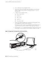
Connecting to a Services Router on page 99
Configuring Basic Settings with J-Web Quick Configuration on page 105
Configuring Basic Settings with a Configuration Editor on page 108
Verifying Basic Connectivity on page 113
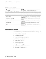
Basic Connectivity Terms
Before configuring basic connectivity, become familiar with the
terms defined in Table 34.
Basic Connectivity Terms
93
Summary of Contents for J4350
Page 14: ...J4350 and J6350 Services Router Getting Started Guide xiv Table of Contents...
Page 22: ...2 J series Overview...
Page 68: ...J4350 and J6350 Services Router Getting Started Guide 48 Field Replaceable PIMs...
Page 75: ...Services Router User Interface Overview Figure 25 J Web Layout Using the J Web Interface 55...
Page 88: ...J4350 and J6350 Services Router Getting Started Guide 68 Using the Command Line Interface...
Page 90: ...70 Installing a Services Router...
Page 100: ...J4350 and J6350 Services Router Getting Started Guide 80 Site Preparation Checklist...
Page 112: ...J4350 and J6350 Services Router Getting Started Guide 92 Powering a Services Router On and Off...
Page 144: ...J4350 and J6350 Services Router Getting Started Guide 124 Verifying Secure Web Access...
Page 162: ...142 Maintaining Services Router Hardware...
Page 194: ...J4350 and J6350 Services Router Getting Started Guide 174 Troubleshooting Hardware Components...
Page 204: ...184 J series Requirements and Specifications...
Page 220: ...J4350 and J6350 Services Router Getting Started Guide 200 ISDN RJ 45 Connector Pinout...
Page 267: ...Part 5 Index Index 247...
Page 268: ...248 Index...


