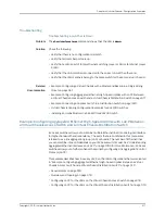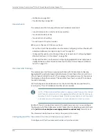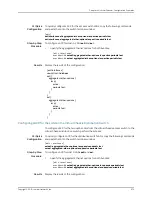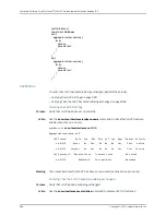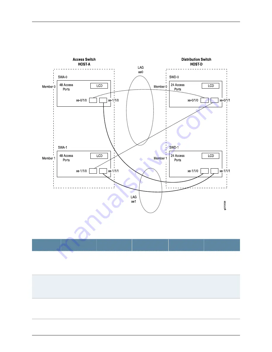
Figure 20: Topology for LAGs Connecting a Virtual Chassis Access Switch
to a Virtual Chassis Distribution Switch
Table 148 on page 973 details the topology used in this configuration example.
Table 148: Components of the Topology for Connecting Virtual Chassis Access Switches to a
Virtual Chassis Distribution Switch
Trunk Port
Member ID
Uplink Module
Base Hardware
Hostname and
VCID
Switch
xe-0/1/0
to SWD-0
xe-0/1/1
to SWD-1
0
One XFP uplink
module
EX4200-48P
switch
Host-A Access
switch
VCID 1
SWA-0
xe-1/1/0
to SWD-0
xe-1/1/1
to SWD-1
1
One XFP uplink
module
EX4200-48P
switch
Host-A Access
switch
VCID 1
SWA-1
xe-0/1/0
to SWA-0
xe-0/1/1
to SWA-1
0
One XFP uplink
module
EX4200 L-24F
switch
Host-D Distribution
switch
VCID 4
SWD-0
973
Copyright © 2010, Juniper Networks, Inc.
Chapter 44: Virtual Chassis—Configuration Examples
Summary of Contents for JUNOS OS 10.3 - SOFTWARE
Page 325: ...CHAPTER 17 Operational Mode Commands for System Setup 229 Copyright 2010 Juniper Networks Inc ...
Page 1323: ...CHAPTER 56 Operational Mode Commands for Interfaces 1227 Copyright 2010 Juniper Networks Inc ...
Page 2841: ...CHAPTER 86 Operational Commands for 802 1X 2745 Copyright 2010 Juniper Networks Inc ...
Page 3367: ...CHAPTER 113 Operational Mode Commands for CoS 3271 Copyright 2010 Juniper Networks Inc ...
Page 3435: ...CHAPTER 120 Operational Mode Commands for PoE 3339 Copyright 2010 Juniper Networks Inc ...
Page 3529: ...CHAPTER 126 Operational Mode Commands for MPLS 3433 Copyright 2010 Juniper Networks Inc ...


