--------------------------------------------------------------------------
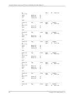
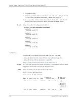
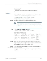
Interface Type Trunk Status Speed Neighbor
or ID (mbps) ID Interface
PIC / Port
vcp-0 Dedicated 1 Up 32000 3 vcp-0
vcp-1 Dedicated 2 Up 32000 3 vcp-1
1/0 Configured 3 Up 1000 0 vcp-255/1/0
1/1 Configured 3 Up 1000 0 vcp-255/1/1
1/2 —1 Down 1000
1/3 —1 Down 1000
fpc3:
--------------------------------------------------------------------------
Interface Type Trunk Status Speed Neighbor
or ID (mbps) ID Interface
PIC / Port
vcp-0 Dedicated 1 Up 32000 2 vcp-0
vcp-1 Dedicated 2 Up 32000 2 vcp-1
1/0 Configured 3 Up 10000 1 vcp-255/1/0
1/1 Configured 3 Up 10000 1 vcp-255/1/1
fpc4:
--------------------------------------------------------------------------
Interface Type Trunk Status Speed Neighbor
or ID (mbps) ID Interface
PIC / Port
vcp-0 Dedicated 1 Down 32000
vcp-1 Dedicated 2 Down 32000
0/20 Configured 3 Up 1000 0 vcp-255/1/2
0/21 Configured 3 Up 1000 0 vcp-255/1/3
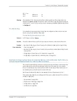
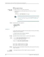
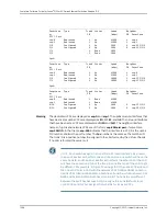
Meaning
The dedicated VCPs are displayed as
vcp-0
and
vcp-1
. The uplink module interfaces that
have been set as uplink VCPs are displayed as
1/0
,
1/1
,
1/2
, and
1/3
. The network interfaces
that have been set as VCPs are displayed as
0/20
and
0/21
. The neighbor interface
names of uplink and network VCPs are of the form
vcp-255/pic/port
—for example,
vcp-255/1/0
. In that name,
vcp-255
indicates that the interface is a VCP,
1
is the uplink
PIC number, and
0
is the port number. The
fpc
number is the same as the member ID.
The trunk ID is a positive number ID assigned to the LAG formed by the Virtual Chassis.
If no LAG is formed, the value is
–1
.
NOTE:
Each switch assigns the trunk IDs to its local interfaces. As a result,
the pair of interfaces that form one end of a LAG on one switch will have the
same trunk ID, and the pair of interfaces that form the other end of the LAG
will have the same trunk ID, but the trunk IDs on either end of the LAG might
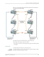
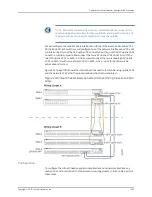
be different. For example, in Figure 23 on page 1001, the uplink VCPs 1/2 and
1/3
on SWA-0 form a LAG with the network VCPs 0/20 and 0/21 on SWA-4.
Uplink VCPs 1/2 and 1/3 on SWA-0 both have trunk ID 4, while network VCPs
0/20
and 0/21 on SWA-4 both have trunk ID 3. The trunk IDs are different
between the switches because SWA-0 assigns the trunk IDs for its local
uplink VCPs and SWA-4 assigns the trunk IDs for its local VCPs.
Copyright © 2010, Juniper Networks, Inc.
1006
Complete Software Guide for Junos
®
OS for EX Series Ethernet Switches, Release 10.3
Summary of Contents for JUNOS OS 10.3 - SOFTWARE
Page 325: ...CHAPTER 17 Operational Mode Commands for System Setup 229 Copyright 2010 Juniper Networks Inc ...
Page 1323: ...CHAPTER 56 Operational Mode Commands for Interfaces 1227 Copyright 2010 Juniper Networks Inc ...
Page 2841: ...CHAPTER 86 Operational Commands for 802 1X 2745 Copyright 2010 Juniper Networks Inc ...
Page 3367: ...CHAPTER 113 Operational Mode Commands for CoS 3271 Copyright 2010 Juniper Networks Inc ...
Page 3435: ...CHAPTER 120 Operational Mode Commands for PoE 3339 Copyright 2010 Juniper Networks Inc ...
Page 3529: ...CHAPTER 126 Operational Mode Commands for MPLS 3433 Copyright 2010 Juniper Networks Inc ...

