1.
Power on the new switch.
2.
Connect a laptop or terminal to the console port of the switch, or use EZSetup on the
standalone switch to specify temporary identification parameters. (When you
interconnect the new member switch with the existing Virtual Chassis configuration,
the master will overwrite and disable any specified parameters that conflict with the
Virtual Chassis parameters or assigned member configuration.)
3.
Use the CLI or the J-Web interface to set the uplink module ports as VCPs.
NOTE:
If you are using a nonprovisioned configuration, you might configure
the new member switch with a mastership priority value that is less than
that of the existing member switches. Doing so ensures that the new
member switch will function in a linecard role when it is included within
the Virtual Chassis configuration.
4.
Power off the new switch.
5.
Interconnect the new member switch to at least one member of the existing Virtual
Chassis configuration using the uplink module ports on each of the switches that have
been configured as VCPs.
6.
Power on the new member switch.
7.
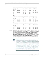
Confirm that the new member switch is now included within the Virtual Chassis
configuration by checking the front-panel display for the member ID. It should display
a member ID that is higher than 0 (1 through 9), because there is already at least one
member of the Virtual Chassis configuration.
NOTE:
If you are using a preprovisioned configuration, the member ID is
automatically assigned to the member's serial number in the configuration
file.
Adding a New Switch to an Existing Preprovisioned Virtual Chassis Configuration Using
Autoprovisioning
Before you begin, be sure you have:
•
Installed the uplink modules needed for the Virtual Chassis configuration.
•
Mounted the new switch in a rack.
•
Ensured that the preprovisioned Virtual Chassis configuration has an active master.
For more information, see “Example: Configuring a Virtual Chassis Using a
Preprovisioned Configuration File” on page 982.
•
On the master, configured the Link Level Discovery Protocol (LLDP) on the uplink
module ports that will be used as VCPs. LLDP is configured by default but might have
been disabled. To configure LLDP, see “Configuring LLDP (CLI Procedure)” on page 2622
or “Configuring LLDP (J-Web Procedure)” on page 2623.
1019
Copyright © 2010, Juniper Networks, Inc.
Chapter 45: Configuring Virtual Chassis
Summary of Contents for JUNOS OS 10.3 - SOFTWARE
Page 325: ...CHAPTER 17 Operational Mode Commands for System Setup 229 Copyright 2010 Juniper Networks Inc ...
Page 1323: ...CHAPTER 56 Operational Mode Commands for Interfaces 1227 Copyright 2010 Juniper Networks Inc ...
Page 2841: ...CHAPTER 86 Operational Commands for 802 1X 2745 Copyright 2010 Juniper Networks Inc ...
Page 3367: ...CHAPTER 113 Operational Mode Commands for CoS 3271 Copyright 2010 Juniper Networks Inc ...
Page 3435: ...CHAPTER 120 Operational Mode Commands for PoE 3339 Copyright 2010 Juniper Networks Inc ...
Page 3529: ...CHAPTER 126 Operational Mode Commands for MPLS 3433 Copyright 2010 Juniper Networks Inc ...


