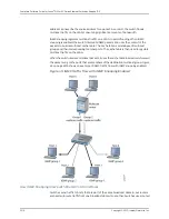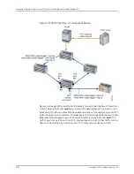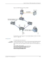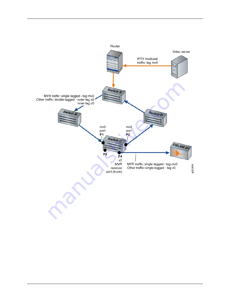
Figure 45: MVR Topology in Transparent Mode
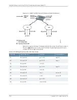
Figure 46 on page 2329 shows the MVR topology in proxy mode. Interfaces P1 and P2 on
switch C belong to MVLAN
mv0
and customer VLAN
c0
. Interface P4 on switch C is an
access port of customer VLAN
c0
. In the upstream direction of the network, only non-IPTV
traffic is being carried on customer VLAN
c0
. Any IPTV traffic requested by hosts on VLAN
c0
is replicated untagged to port P4 based on streams received in MVLAN
mv0
. IPTV
traffic flows from port P4 out to an IPTV-enabled device in Host 1. Other traffic, such as
data and voice traffic, also flows from port P4 to other network devices in Host 1.
Copyright © 2010, Juniper Networks, Inc.
2328
Complete Software Guide for Junos
®
OS for EX Series Ethernet Switches, Release 10.3
Summary of Contents for JUNOS OS 10.3 - SOFTWARE
Page 325: ...CHAPTER 17 Operational Mode Commands for System Setup 229 Copyright 2010 Juniper Networks Inc ...
Page 1323: ...CHAPTER 56 Operational Mode Commands for Interfaces 1227 Copyright 2010 Juniper Networks Inc ...
Page 2841: ...CHAPTER 86 Operational Commands for 802 1X 2745 Copyright 2010 Juniper Networks Inc ...
Page 3367: ...CHAPTER 113 Operational Mode Commands for CoS 3271 Copyright 2010 Juniper Networks Inc ...
Page 3435: ...CHAPTER 120 Operational Mode Commands for PoE 3339 Copyright 2010 Juniper Networks Inc ...
Page 3529: ...CHAPTER 126 Operational Mode Commands for MPLS 3433 Copyright 2010 Juniper Networks Inc ...


