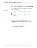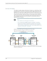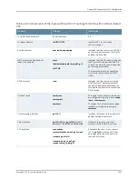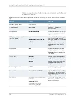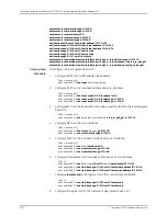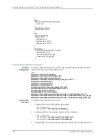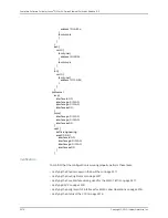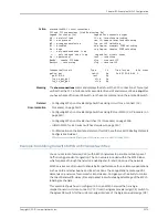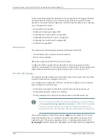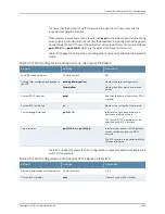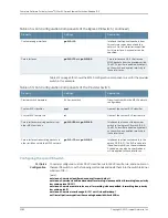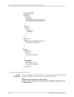
set protocols mpls interface ge-0/0/5.0
set protocols mpls interface ge-0/0/6.0
set protocols rsvp interface lo0.0
set protocols rsvp interface ge-0/0/5.0
set protocols rsvp interface ge-0/0/6.0
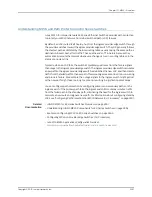
set interfaces lo0 unit 0 family inet address 127.1.1.1/32
set interfaces ge-0/0/5 unit 0 family inet address 10.1.5.1/24
set interfaces ge-0/0/6 unit 0 family inet address 10.1.6.1/24
set interfaces ge-0/0/5 unit 0 family mpls
set interfaces ge-0/0/6 unit 0 family mpls
set interfaces ge-0/0/1 unit 0 family ccc
set protocols connections remote-interface-switch ge-1–to-pe2 interface ge-0/0/1.0
set protocols connections remote-interface-switch ge-1–to-pe2 transmit-lsp lsp_to_pe2_ge1
set protocols connections remote-interface-switch ge-1–to-pe2 receive-lsp lsp_to_pe1_ge1
Step-by-Step
Procedure
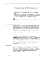
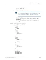
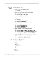
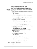
To configure the local ingress PE switch:
1.
Configure OSPF with traffic engineering enabled:
[edit protocols]
user@switchPE-1#
set ospf
traffic-engineering
2.
Configure OSPF on the loopback address and core interfaces:
[edit protocols]
user@switchPE-1#
set ospf area 0.0.0.0 interface lo0.0
user@switchPE-1#
set ospf area 0.0.0.0 interface ge-0/0/5.0
user@switchPE-1#
set ospf area 0.0.0.0 interface ge-0/0/6.0
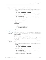
3.
Configure MPLS on the local switch with a label-switched path to the remote egress
PE switch:
[edit protocols]
user@switchPE-1#
set
mpls label-switched-path
lsp_to_pe2_ge1 to 127.1.1.3
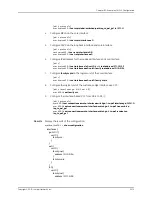
4.
Configure MPLS on the core interfaces:
[edit protocols]
user@switchPE-1#
set mpls
interface
ge-0/0/5.0
user@switchPE-1#
set mpls interface ge-0/0/6.0
5.
Configure RSVP on the loopback interface and core interfaces:
[edit protocols]
user@switchPE-1#
set
rsvp
interface lo0.0
user@switchPE-1#
set rsvp interface ge-0/0/5.0
user@switchPE-1#
set rsvp interface ge-0/0/6.0
6.
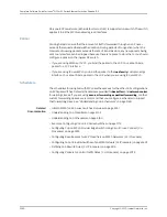
Configure IP addresses for the loopback interface and core interfaces:
[edit]
user@switchPE-1#
set
interfaces
lo0 unit 0
family
inet address 127.1.1.1/32
user@switchPE-1#
set interfaces ge-0/0/5 unit 0 family inet address 10.1.5.1/24
user@switchPE-1#
set interfaces ge-0/0/6 unit 0 family inet address 10.1.6.1/24
7.
Configure
family mpls
on the logical unit of the core interface addresses:
[edit]
user@switchPE-1#
set interfaces ge-0/0/5 unit 0 family mpls
user@switchPE-1#
set interfaces ge-0/0/6 unit 0 family mpls
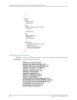
8.
Configure the logical unit of the customer-edge interface as a CCC:
Copyright © 2010, Juniper Networks, Inc.
3370
Complete Software Guide for Junos
®
OS for EX Series Ethernet Switches, Release 10.3
Summary of Contents for JUNOS OS 10.3 - SOFTWARE
Page 325: ...CHAPTER 17 Operational Mode Commands for System Setup 229 Copyright 2010 Juniper Networks Inc ...
Page 1323: ...CHAPTER 56 Operational Mode Commands for Interfaces 1227 Copyright 2010 Juniper Networks Inc ...
Page 2841: ...CHAPTER 86 Operational Commands for 802 1X 2745 Copyright 2010 Juniper Networks Inc ...
Page 3367: ...CHAPTER 113 Operational Mode Commands for CoS 3271 Copyright 2010 Juniper Networks Inc ...
Page 3435: ...CHAPTER 120 Operational Mode Commands for PoE 3339 Copyright 2010 Juniper Networks Inc ...
Page 3529: ...CHAPTER 126 Operational Mode Commands for MPLS 3433 Copyright 2010 Juniper Networks Inc ...

