Establishing a High Availability Connection
27
Installing the Device
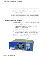
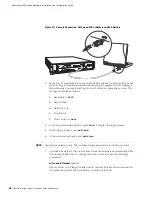
To connect the DC power supply to a grounding point at your site:
1.
Remove the hex nut on the grounding screw.
2.
Place the ground lug on the screw and tighten the hex nut securely.
3.
Connect the other end of the grounding lug wire to a grounding point at your
site.
To connect DC power feeds to the terminal blocks:
1.
Loosen the retaining screws on each terminal block.
2.
Insert the 0V DC (positive voltage) return wire into the center COM connector
and the -48V DC power feed wire into either the left or right connector.
3.
Fasten the screws over the connectors.
4.
Turn the power switches on.
Establishing a High Availability Connection
To ensure continuous traffic flow in the event of a system failure, you can cable and
configure two security devices in a redundant cluster, with one device acting as a
master and the other as its backup. The master propagates all its network,
configuration and session information to the backup. Should the master fail, the
backup is promoted to master and takes over the traffic processing.
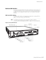
To physically connect the master and backup devices, the management modules
provide a pair of high availability (HA) ports. To connect the NetScreen-5000 Series
systems, you can use the provided Gigabit Ethernet SFP cable. Use this cable to
connect the HA1 port on one system to the HA1 port on another system. Though
you cannot connect HA ports between 5000-M and 5000-M2 management
modules, you can connect HA ports between the same type of management
module. For example, a 5000-M management module to another 5000-M
management module.
For information on setting up HA configurations, refer to the
Concepts & Examples
ScreenOS Reference Guide
.
WARNING:
You must shut off the electric current to the DC feed wires before
connecting the wires to the power supplies. Also, make sure that the power switch
is in the off position.
NOTE:
If there are multiple power supplies in the NetScreen-5000 Series system and any
of them are off, then the Alarm LED on the management module glows red. This
alarm indicates that maximum system stability requires all installed power
supplies to be operational.


