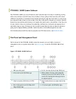
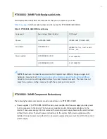
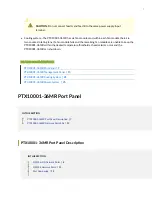
background image

PTX10001-36MR Packet Transport
Router Hardware Guide

Published

2022-09-15

Summary of Contents for PTX10001-36MR

Page 1: ...PTX10001 36MR Packet Transport Router Hardware Guide Published 2022 09 15...

Page 2: ...Hardware Guide Copyright 2022 Juniper Networks Inc All rights reserved The information in this document is current as of the date on the title page YEAR 2000 NOTICE Juniper Networks hardware and soft...

Page 3: ...Panel 7 PTX10001 36MR Port Panel Description 7 PTX10001 36MR Network Port LEDs 13 PTX10001 36MR Management Panel 15 PTX10001 36MR Management Panel Description 15 PTX10001 36MR Management Panel LEDs 1...

Page 4: ...ices 59 Fiber Optic Cable Signal Loss Attenuation and Dispersion 66 Calculating Power Budget and Power Margin for Fiber Optic Cables 68 How to Calculate Power Budget for Fiber Optic Cables 68 How to C...

Page 5: ...SLAs 97 Perform the Initial Software Configuration for the PTX10001 36MR 98 Power Off the PTX10001 36MR 100 Power Off the AC Powered PTX10001 36MR 101 Power Off the DC Powered PTX10001 36MR 102 4 Remo...

Page 6: ...turn the Chassis or Components Contact Customer Support 135 Return the PTX10001 36MR Chassis or Components 136 Locate the Serial Number on a PTX10001 36MR Chassis or Component 136 List the Chassis and...

Page 7: ...Open Port Apertures Warning 164 Maintenance and Operational Safety Guidelines and Warnings 165 General Electrical Safety Guidelines and Warnings 171 Action to Take After an Electrical Accident 172 Pre...

Page 8: ...liance Statements 184 PTX10001 36MR Agency Approvals 185 Compliance Statements for EMC Requirements 186 Compliance Statements for Environmental Requirements 189 Compliance Statements for NEBS 189 PTX1...

Page 9: ...utine maintenance and to troubleshoot PTX10001 36MR Packet Transport Routers After completing the installation and basic configuration procedures covered in this guide refer to the Junos OS Evolved do...

Page 10: ...1 CHAPTER Overview PTX10001 36MR System Overview 2 PTX10001 36MR Port Panel 7 PTX10001 36MR Management Panel 15 PTX10001 36MR Cooling System 21 PTX10001 36MR Power System 25...

Page 11: ...ks PTX10001 36MR is a fixed configuration router that features 36 network ports that provide high density and cost efficient 100 Gigabit and 400 Gigabit Ethernet GbE ports in a low profile 1 U form fa...

Page 12: ...t SLAs across the core Space efficiency The PTX10001 36MR s ultra compact 1 U form factor efficiency is a critical requirement for space and power constrained internet exchange locations remote centra...

Page 13: ...rastructure is entirely modernized giving you the high availability portability faster innovation and simplified upgrades you need For information about which features are supported on PTX Series devi...

Page 14: ...of six fan modules as well as fans housed in the power supplies Each fan module has dual counter rotating fans These fan modules can be hot swapped and hot inserted meaning that you do not need to pow...

Page 15: ...per net customers support tools updateinstallbase Failure to do so can result in significant delays if you need replacement parts This note does not apply if you replace existing components with the s...

Page 16: ...R within the desired temperature thresholds chassis alarms occur and the PTX10001 36MR can shut down RELATED DOCUMENTATION PTX10001 36MR Port Panel 7 PTX10001 36MR Management Panel 15 PTX10001 36MR Co...

Page 17: ...X10001 36MR port panel Figure 3 PTX10001 36MR Port Panel 1 ESD grounding point 6 RJ 45 console and time of day TOD port 2 12 network ports QSFP28 cages 7 Offline button Pressing and holding this butto...

Page 18: ...restriction is due to thermal limitations NOTE Be aware of the following thermal restrictions for the QDD 400G ZR and QDD 400G ZR M transceivers When operating at an ambient temperature of 23 C or gre...

Page 19: ...D ports Table 2 QSFP56 DD Ports Maximum Supported Ports at Each Interface Speed Interface Type Maximum Supported Ports NOTE To achieve maximum ports break out cables maybe required 400GbE 24 100GbE 96...

Page 20: ...ed by the QSFP28 ports Table 3 QSFP28 Ports Maximum Supported Ports at Each Interface Speed Interface Type Maximum Supported Ports NOTE To achieve maximum ports break out cables might be required 100G...

Page 21: ...the PTX10001 36MR network ports are divided into the 3 PICs Figure 4 PTX10001 36MR PIC Locations How to Configure the QSFP28 Ports for 10 Gbps 25 Gbps and 40 Gbps Speeds The QSFP28 ports support 10 G...

Page 22: ...ps 25 Gbps or 40 Gbps Port Speeds Port Speed Supported Port Number Corresponding Port Number That Must Be Powerd Off 40 Gbps 4 5 6 7 25 Gbps 4 5 6 7 10 Gbps 4 5 6 7 PTX10001 36MR Network Port LEDs Eac...

Page 23: ...LED Color LED State Description Unlit Off The port is administratively disabled there is no power the link is down or a transceiver is not present Green On steadily A link is established and all chann...

Page 24: ...eparate from production traffic PTX10001 36MR Management Panel Description The PTX10001 36MR management panel is located to the right of the network ports Figure 6 on page 16 shows the connections and...

Page 25: ...n 4 seconds turns the device off Pressing the button again turns the device back on 3 Clock connectors 10 MHz and 1 PPS 8 Reset button do not use unless directed by JTAC 4 RJ 45 management port 10 Mbp...

Page 26: ...Port LEDs The PTX10001 36MR has two 200 GB Serial Advanced Technology Attachment SATA solid state drives SSD Each SSD has its own status LED The LEDs are located on the management panel next to the ch...

Page 27: ...ered off Green On steadily Junos OS Evolved is loaded on the device Green Blinking Junos OS Evolved is being loaded on the device ALM Alarm Unlit Off The device is halted or there is no alarm Red On s...

Page 28: ...nd monitor the status LEDs to ensure that Junos OS Evolved boots properly Yellow Blinking Both a major and a minor alarm is occurring on the device OK FAIL Green On steadily There are no fault conditi...

Page 29: ...45 management port LEDs Table 8 PTX10001 36MR RJ 45 Management Port LEDs LED Color State Description Status Unlit Off No link is established or the port speed is 10 Mbps Yellow On steadily The port sp...

Page 30: ...ules in the PTX10001 36MR The airflow direction on the PTX10001 36MR is airflow out air comes into the device through the vents in the front port panel The fan modules in the PTX10001 36MR are hot ins...

Page 31: ...fan module for the PTX10001 36MR Figure 10 PTX10001 36MR Fan Module You remove and replace a fan module from the back end of the chassis During replacement the device continues to operate for four mi...

Page 32: ...OUT labels in devices in which the fan modules have AIR OUT labels Airflow Through the Chassis In the PTX10001 36MR cooling system cool air enters through the vents in the port panel and hot air exha...

Page 33: ...le LEDs You can check the status of fan modules through the show system alarms command or by looking at the LEDs next to each fan module Figure 12 on page 24 shows the location of the LED on the fan m...

Page 34: ...01 36MR DC Power Supply Description 38 The PTX10001 36MR is powered by 3000 W redundant AC HDVC or DC power supplies that are preinstalled at the factory The PTX10001 36MR is powered by two power supp...

Page 35: ...or HVDC power The power supplies automatically detect whether there is AC or HVDC input voltage and manage the power accordingly AC power can be 180 305 VAC input voltage and HVDC power can be 190 40...

Page 36: ...r supply module components Figure 14 PTX10001 36MR AC HVDC Power Supply 1 Plug power connector 3 Ejector lever 2 Status LED 4 Orange handle CAUTION To avoid electrical injury carefully follow instruct...

Page 37: ...HVDC power supply module uses an amber and green bicolor LED to indicate the operating state see Table 11 on page 28 Table 11 PTX10001 36MR AC HVDC Power Supply Status LED Description LED Color LED St...

Page 38: ...spot temperature is greater than 95 F 35 C high power high current or slow fan less than 1200 rpm You can get additional information about the status of the power supply modules using the show chassi...

Page 39: ...6MR operates within the AC HVDC input voltage range listed in Table 12 on page 30 The PTX10001 36MR power consumption is listed in Table 13 on page 30 Table 12 PTX10001 36MR AC HVDC Power Specificatio...

Page 40: ...ional Electrical Code NEC Sections 400 8 NFPA 75 5 2 2 and 210 52 and Canadian Electrical Code CEC Section 4 010 3 The cords that can be ordered for the PTX10001 36MR are in compliance Table 14 on pag...

Page 41: ...derson 3 5958p4 CBL JNP SG4 C20 CH Europe except Italy Switzerland and United Kingdom 20 A 250 VAC CEE 7 7 STRAIGHT CBL JNP SG4 EU Great Britain 13 A 250 VAC BS1363 CBL JNP SG4 UK India 16 A 250 VAC S...

Page 42: ...Anderson 3 5958p4 CBL JNP SG4 C20 North America 16 A 250 VAC Locking NEMA L6 20P CBL JNP SG4 US L North America 16 A 250 VAC NEMA 6 20P CBL JNP SG4 US North America 15 A 277 V NEMA I7 20P CBL JNP SG4...

Page 43: ...fault Power Cords Supplied Locale Spare Juniper Model Number Graphic Australia Cook Islands Fiji Kiribati Nauru New Zealand Papua New Guinea Samoa Tonga and Vanuatu CBL JNP SG4 AU Brazil CBL JNP SG4 B...

Page 44: ...orgia Germany Ghana Gibraltar Greece Greenland Guinea Guinea Bissau Hungary Iceland Indonesia Iran Iraq Isle of Man Ivory Coast Jordan Kuwait Kazakhstan Latvia Libya Lithuania Luxembourg Macau Macedon...

Page 45: ...R Default Power Cords Supplied Continued Locale Spare Juniper Model Number Graphic Israel CBL JNP SG4 IL Chile Italy and San Marino CBL JNP SG4 IT South Africa CBL JNP SG4 SA Maldives and United Kingd...

Page 46: ...Antilles Niger Panama Peru Philippines Puerto Rico Saudi Arabia Taiwan Thailand Trinidad and Tobago U S Virgin Islands United States and Venezuela CBL JNP SG4 US L Table 16 PTX10001 36MR HVDC Cable Sp...

Page 47: ...bles 42 PTX10001 36MR DC Power Lugs 43 View Power Statistics 44 The PTX10001 36MR DC power supplies are hot removable and hot insertable FRUs Each 3000 W power supply module has a single DC input and...

Page 48: ...module has a status LED on the power supply module faceplate see Figure 17 on page 39 Figure 17 PTX10001 36MR DC Power Supply Status LED Location 1 Power supply status LED Table 17 on page 39 describe...

Page 49: ...PTX10001 36MR DC power supply module can operate with an input current of 80 A or 60 A You select the input rating by moving the DC input current selector DIP switch to the desired setting Refer to F...

Page 50: ...the available input source we recommend that the 48 VDC facility DC source be equipped with a circuit breaker rated at a minimum of 60 A 48 VDC or 80 A 48 VDC or as required by local code Table 18 PTX...

Page 51: ...0 V Input voltage 40 V to 72 V 60 A DC mode The power supply module is powered off and won t turn on when the system is powering up Normal operation PTX10001 36MR with two power supply modules The pow...

Page 52: ...ARNING DC power cables must not block access to PTX10001 36MR components or drape where people could trip on them PTX10001 36MR DC Power Lugs The accessory box shipped with the PTX10001 36MR includes...

Page 53: ...all the PTX10001 36MR a licensed electrician must attach a cable lug to the power cables that you supply A cable with an incorrectly attached lug can damage the PTX10001 36MR View Power Statistics You...

Page 54: ...hassis Power Voltage V Power W Total Input Power 1230 PSM 0 Input 1 53 584 Output 12 07 531 43 Capacity 3000 W maximum 3000 W PSM 1 Input 1 53 646 Output 12 07 626 14 Capacity 3000 W maximum 3000 W It...

Page 55: ...on and Specifications PTX10001 36MR Site Preparation Checklist 47 PTX10001 36MR Site Guidelines and Requirements 48 PTX10001 36MR Network Cable and Transceiver Planning 58 PTX10001 36MR Management Cab...

Page 56: ...l Requirements and Specifications on page 49 Power Measure the distance between external power sources and the router installation site Calculate the power consumption and requirements Table 12 on pag...

Page 57: ...sceiver Support for the PTX10001 36MR on page 58 Cable and Connector Specifications for MX and PTX Series Devices on page 59 Plan the cable routing and management RELATED DOCUMENTATION PTX10001 36MR I...

Page 58: ...environment Follow these environmental guidelines The site must be as dust free as possible because dust can clog air intake vents and filters reducing the efficiency of the PTX10001 36MR cooling syst...

Page 59: ...as such as dedicated equipment rooms and equipment closets in accordance with Articles 110 16 110 17 and 110 18 of the National Electrical Code ANSI NFPA 70 General Site Guidelines Efficient device op...

Page 60: ...arate protective earthing terminal must be permanently connected to earth ground for installations that require a separate grounding conductor to the chassis WARNING To comply with GR 1089 requirement...

Page 61: ...information about the airflow through the chassis If you are mounting a PTX10001 36MR in a rack with other equipment ensure that the exhaust from other equipment does not blow into the intake vents o...

Page 62: ...cal surge suppression devices Avertissement Vous devez tablir un environnement prot g et convenablement mis la terre et utiliser des dispositifs de parasurtension Table 24 Site Electrical Wiring Guide...

Page 63: ...sceptible to problems with electromagnetic compatibility EMC particularly from lightning or radio transmitters seek expert advice Strong sources of electromagnetic interference EMI can cause Destructi...

Page 64: ...EIA 310 D published by the Electronics Components Industry Association http www ecianow org Use a 600 mm rack as defined in the four part Equipment Engineering EE European telecommunications standard...

Page 65: ...abinet that contains a four post 19 in open rack as defined in Cabinets Racks Panels and Associated Equipment document number EIA 310 D published by the Electronics Industry Association Cabinet requir...

Page 66: ...through the chassis If the cabinet contains a top or doors perforations in these elements assist with removing the hot air exhaust The PTX10001 36MR fans exhaust hot air through the vents on the fans...

Page 67: ...cables AOC and DAC breakout cables DACBO See PTX10001 36MR Port Panel on page 7 for more information about the network ports You can find information about the pluggable transceivers supported on your...

Page 68: ...use of third party optical modules or cables is the users responsibility Juniper Networks will accept no liability for any damage caused due to such use Cable and Connector Specifications for MX and...

Page 69: ...rrectly Physical contact PC refers to fiber that has been polished flat Angled physical contact APC refers to fiber that has been polished at an angle Ultra physical contact UPC refers to fiber that h...

Page 70: ...Ribbon Patch Cables Continued Fiber Signal 5 Unused 6 Unused 7 Unused 8 Unused 9 Rx3 Receive 10 Rx2 Receive 11 Rx1 Receive 12 Rx0 Receive Table 28 Cable Pinouts for 12 Fiber Ribbon Patch Cables MPO Pi...

Page 71: ...ample 4x10GBASE LR to 10GBASE LR or 4x10GBASE SR to 10GBASE SR SFP transceivers The breakout cable is constructed out of a 12 fiber ribbon fiber optic cable The ribbon cable splits from a single cable...

Page 72: ...uplex 1 2 Tx on LC Duplex 2 3 Tx on LC Duplex 3 4 Tx on LC Duplex 4 5 Unused 6 Unused 7 Unused 8 Unused 9 Rx on LC Duplex 4 10 Rx on LC Duplex 3 11 Rx on LC Duplex 2 12 Rx on LC Duplex 1 12 Ribbon Pat...

Page 73: ...MTP12 FF M1M 3 m MTP12 FF M3M 5 m MTP12 FF M5M 10 m MTP12 FF M10M Socket MPO APC to socket MPO APC key up to key up SMF 1 m MTP12 FF S1M 3 m MTP12 FF S3M 5 m MTP12 FF S5M 10 m MTP12 FF S10M 12 ribbon...

Page 74: ...rect polarity Vendors refer to these crossover cables as key up to key up latch up to latch up Type B or Method B If you are using patch panels between two transceivers ensure that the proper polarity...

Page 75: ...to100GBASE LR4 The patch cable is one fiber pair with two LC duplex connectors at opposite ends LC duplex connectors are also used with 12 fiber ribbon breakout cables as described in 12 Fiber Ribbon...

Page 76: ...ight reaching the receiver with enough power to be demodulated correctly Attenuation is the reduction in power of the light signal as it is transmitted Attenuation is caused by passive media component...

Page 77: ...information about the pluggable transceivers supported on your Juniper Networks device To calculate the power budget and power margin perform the following tasks How to Calculate Power Budget for Fib...

Page 78: ...al loss caused by equipment and other factors refer to vendor documentation Table 31 Estimated Values for Factors Causing Link Loss Link Loss Factor Estimated Link Loss Value Higher order mode losses...

Page 79: ...8 km 0 5 dB km 7 0 5 dB PM 13 dB 4 dB 3 5 dB PM 5 5 dB In both examples the calculated power margin is greater than zero indicating that the link has sufficient power for transmission and does not exc...

Page 80: ...ections for the PTX10001 36MR Port on PTX10001 36MR Cable Specification Cable Supplied Maximum Length Device Receptacle Console CON ToD port RS 232 EIA 232 serial cable One 7 foot 2 13 meter long RJ 4...

Page 81: ...ransmit receive data pair 4 8 TRP4 Transmit receive data pair 4 Console and ToD Port Connector Pinouts for the PTX10001 36MR The console port labeled CON ToD is an RS 232 serial interface that uses an...

Page 82: ...pins as a ToD universal asynchronous receiver transmitter UART by using breakout cables 3 RxD Input Receive data 4 Signal Ground Signal ground 5 Signal Ground Signal ground 6 TxD Output Transmit data...

Page 83: ...ve the USB flash drive before upgrading Junos OS Evolved or rebooting a PTX10001 36MR Failure to do so could expose your router to unpredictable behavior RELATED DOCUMENTATION PTX10001 36MR Management...

Page 84: ...view 76 Unpack and Mount the PTX10001 36MR 78 Connect the PTX10001 36MR to Power 85 Connect the PTX10001 36MR to External Devices 95 Register Products Mandatory to Validate SLAs 97 Perform the Initial...

Page 85: ...d mounting is primarily used in enclosed cabinets to allow room for cabling To install and connect a PTX10001 36MR 1 Unpack the PTX10001 36MR and verify the components received See Unpack the PTX10001...

Page 86: ...ng documentation PTX10001 36MR Site Preparation Checklist on page 47 PTX10001 36MR Clearance Requirements for Airflow and Hardware Maintenance on page 52 PTX10001 36MR Rack Requirements on page 54 PTX...

Page 87: ...e that your footing is solid RELATED DOCUMENTATION Unpack and Mount the PTX10001 36MR 78 Unpack and Mount the PTX10001 36MR IN THIS SECTION Unpack the PTX10001 36MR 78 Mount the PTX10001 36MR in a Rac...

Page 88: ...mount kit 2 side mounting blades and 2 side mounting rails NOTE If you are installing the PTX10001 36MR on a two post rack you must order the 2 post rack mount kit separately Sixteen flathead screws f...

Page 89: ...rack rails can be spaced apart is 23 6 in 60 cm front to back The maximum distance the front and rear rack rails can be spaced apart is 31 5 in 80 cm front to back The remainder of this topic uses rac...

Page 90: ...pair of front mounting rails and rear mounting blades These mounting blades support the rear of the chassis and must be installed ordered separately Screws to secure the mounting rail to the chassis 1...

Page 91: ...ave one person grasp both sides of the device lift it and position it in the rack so that the front bracket is aligned with the rack holes 7 Have a second person secure the front of the device to the...

Page 92: ...secure the chassis and mounting bracket to the rack not provided Screwdriver appropriate for the rack mounting screws not provided Two power cords with plugs appropriate to your geographical location...

Page 93: ...Figure 26 Attach the Two Post Mounting Brackets to the PTX10001 36MR 4 Attach the mounting bracket to the device using the mounting screws Tighten the screws 5 Repeat Step 3 and Step 4 on the opposite...

Page 94: ...e rack Figure 28 The PTX10001 36MR Secured in a Two Post Rack RELATED DOCUMENTATION PTX10001 36MR Installation Overview 76 Connect the PTX10001 36MR to Ground 86 Connect the PTX10001 36MR to Power IN...

Page 95: ...grounding lug to the switch See Unpack and Mount the PTX10001 36MR on page 78 NOTE You must install the PTX10001 36MR in a restricted access location and ensure that the chassis is always properly gr...

Page 96: ...re 29 on page 87 shows the location of the chassis grounding point Figure 29 PTX10001 36MR Grounding Points 2 Secure the grounding lug to the protective earthing terminal with the washers and screws S...

Page 97: ...whether there is AC or HVDC input voltage and manage the power accordingly Each 3000 W AC HVDC power supply module has a single AC or HVDC input and provides 12 V of power to the system The power sup...

Page 98: ...sition NOTE The device powers on as soon as power is provided to the power supply There is no power switch on the device 6 Insert the power cord plug into an AC power source outlet 7 If the AC power s...

Page 99: ...ian must attach a cable lug to the grounding and power cables that you supply A cable with an incorrectly attached lug can damage the router for example by causing a short circuit NOTE To meet safety...

Page 100: ...emove and replace it without powering off the router or disrupting router functions You do however need to remove power from the power supply before attempting to remove the unit WARNING A DC powered...

Page 101: ...al block cover 3 DC input current selector DIP switch 4 Open the cable manager latch on the terminal block cover of a power supply 5 Use a Phillips screwdriver to loosen the screw holding the cable ma...

Page 102: ...st use an appropriate torque controlled tool to tighten the hexnuts on the DC power cable connector Do not overtighten the screws Applying excessive torque damages the terminal block and the wiring tr...

Page 103: ...ose the cable manager latch to hold the power cables in place See Figure 36 on page 94 WARNING Ensure that the power cables do not block access to device components or drape where people could trip ov...

Page 104: ...e has one management port a 10 100 1000BASE T RJ 45 port for copper connections You use the management port to connect the device to a network for out of band management NOTE You cannot use the manage...

Page 105: ...a DB 9 plug connector pin and you want to connect your laptop or PC directly to the PTX10001 36MR use a combination of the RJ 45 cable and RJ 45 to DB 9 adapter provided and a USB to DB 9 plug adapter...

Page 106: ...er Networks hardware products and changes to an existing installed product using the Juniper Networks website to activate your hardware replacement service level agreements SLAs CAUTION Register produ...

Page 107: ...visioning ZTP To provision the PTX10001 36MR using ZTP you ll need access to a Dynamic Host Control Protocol DHCP server and a File Transfer Protocol anonymous FTP Hypertext Transfer Protocol HTTP or...

Page 108: ...ation marks edit root set system host name host name 7 Configure the default gateway edit root set routing options static route default next hop address 8 Configure the IP address and prefix length fo...

Page 109: ...6MR Management Cable Specifications and Pinouts 70 Power Off the PTX10001 36MR IN THIS SECTION Power Off the AC Powered PTX10001 36MR 101 Power Off the DC Powered PTX10001 36MR 102 Ensure that you hav...

Page 110: ...nagement device by issuing the request system halt operational mode CLI command This command shuts down Junos OS Evolved gracefully and preserves system state information A message appears on the cons...

Page 111: ...nect a management device to the console COM ToD port on a PTX10001 36MR by following the instructions in Connect the PTX10001 36MR to a Management Console on page 96 Connect a management device to the...

Page 112: ...with this procedure 3 4 Turn off the circuit breaker for the DC power source CAUTION Turn off the circuit breaker for the HVDC power source before disconnecting the power cord from the power supply Un...

Page 113: ...nstall and Maintain Components Maintain the PTX10001 36MR Fan Modules 105 Maintain the PTX10001 36MR Power Supplies 108 Maintain the PTX10001 36MR Transceivers and Fiber Optic Cables 114 Uninstall the...

Page 114: ...dules in a PTX10001 36MR are hot removable and hot insertable field replaceable units FRUs you can remove and replace them without powering off the PTX10001 36MR or disrupting routing functions CAUTIO...

Page 115: ...aced on a flat stable surface See Figure 40 on page 106 Figure 40 Remove a Fan Module from a PTX10001 36MR NOTE When a fan module is removed the CLI message Fan Blower is Absent is logged in the syste...

Page 116: ...ap to your bare wrist and connect the strap to one of the ESD points on the chassis 2 Taking care not to touch the connectors remove the fan module from its bag 3 Align the module with the open slot o...

Page 117: ...ng functions CAUTION Do not mix AC HVDC and DC power supplies in the same chassis Here are the parts and tools you ll need to replace a power supply ESD grounding strap provided Antistatic bag or an a...

Page 118: ...c bag or the antistatic mat on a flat stable surface 2 Wrap and fasten one end of the ESD wrist strap around your bare wrist and connect the other end of the strap to the ESD point on the device 3 Dis...

Page 119: ...nstall the AC HVDC Power Supply in the PTX10001 36MR CAUTION Install the power supply within two minute of removal to prevent chassis overheating Before removing the power supply ensure you have a rep...

Page 120: ...r net customers support tools updateinstallbase Failure to do so can result in significant delays if you need replacement parts This note does not apply if you replace existing components with the sam...

Page 121: ...e 2 Wrap and fasten one end of the ESD wrist strap around your bare wrist and connect the other end of the strap to the ESD point on the device 3 Turn off the circuit breaker for the power feed to the...

Page 122: ...ve plastic wrap peel and remove the plastic wrap from all four sides of the power supply 3 Taking care not to touch power supply components pins leads or solder connections remove the power supply fro...

Page 123: ...1 36MR Power System 25 Connect the PTX10001 36MR to Power 85 Maintain the PTX10001 36MR Transceivers and Fiber Optic Cables IN THIS SECTION Remove a QSFP28 or QSFP56 DD Transceiver 115 Install a QSFP2...

Page 124: ...re 47 on page 115 1 Place an electrostatic bag or antistatic mat on a flat stable surface to receive the QSFP28 transceiver Have ready a rubber safety cap for the transceiver and the cable 2 Attach an...

Page 125: ...lace the transceiver on the antistatic mat or in the electrostatic bag Install a QSFP28 or QSFP56 DD Transceiver To install a replacement QSFP28 or QSFP56 DD transceiver 1 Attach an electrostatic disc...

Page 126: ...nd its minimum bend radius An arc smaller than a few inches in diameter can damage the cable and cause problems that are difficult to diagnose 7 Verify that the status LEDs on the indicate that the QS...

Page 127: ...move the cable connected to the transceiver see Disconnect a Fiber Optic Cable from the PTX10001 36MR on page 122 Cover the transceiver and the end of each fiber optic cable connector with a rubber sa...

Page 128: ...stable surface 9 Place the dust cover over the empty port or install the replacement transceiver Install a Transceiver Before you install a transceiver in a device ensure that you have taken the nece...

Page 129: ...liability for any damage caused due to such use Figure 49 on page 122 shows how to install a SFP or QSFP transceiver To install a transceiver CAUTION To prevent electrostatic discharge ESD damage to...

Page 130: ...age your eyes CAUTION Do not leave a fiber optic transceiver uncovered except when inserting or removing cable The safety cap keeps the port clean and protects your eyes from accidental exposure to la...

Page 131: ...01 36MR ensure that you have taken the necessary precautions for safe handling of lasers see Radiation from Open Port Apertures Warning on page 164 and Laser and LED Safety Guidelines and Warnings on...

Page 132: ...rom the transceiver 3 Cover the transceiver with a rubber safety cap LASER WARNING Do not leave a fiber optic transceiver uncovered except when inserting or removing a cable The rubber safety cap keep...

Page 133: ...s beyond their minimum bend radius Bending the cables beyond their minimum bend radius can damage the cables and cause problems that are difficult to diagnose CAUTION Do not let fiber optic cables han...

Page 134: ...as RIFOCS Fiber Optic Adaptor Cleaning Wands part number 946 Follow the directions in the cleaning kit you use After cleaning the transceiver make sure that the connector tip of the fiber optic cable...

Page 135: ...re that you have disconnected any cables or wires attached to the PTX10001 36MR see Disconnect a Fiber Optic Cable from the PTX10001 36MR on page 122 To remove a PTX10001 36MR from a rack 1 Have one p...

Page 136: ...5 CHAPTER Troubleshoot the Hardware Troubleshoot the PTX10001 36MR 128...

Page 137: ...the PTX10001 36MR For more information see the following topics PTX10001 36MR Chassis Status LEDs on page 18 PTX10001 36MR Management Panel LEDs on page 16 PTX10001 36MR Network Port LEDs on page 13...

Page 138: ...on the PTX10001 36MR System alarms indicate a failure on the device or one of its components System alarms are preset and cannot be modified System alarms on PTX10001 36MR devices have two severity le...

Page 139: ...oblem persists replace the fan module Minor yellow Fan Blower Absent Check the system log for the message fan number Absent where fan number can be 0 1 2 3 4 or 5 Install the fan module Power supplies...

Page 140: ...customer support Minor yellow PEM pem number Absent A power supply is not installed Install a supported power supply in the appropriate slot PEM pem number Power Supply Type Mismatch Check if there is...

Page 141: ...yellow sensor location Temp Sensor Too Warm For information only Check environmental conditions and alarms on other devices Ensure that environmental factors such as hot air blowing around the equipm...

Page 142: ...fective Replace the cable if required If you are unable to resolve the problem open a support case by using the Case Manager link at https www juniper net support or call 1 888 314 5822 toll free US o...

Page 143: ...6 CHAPTER Contact Customer Support and Return the Chassis or Components Contact Customer Support 135 Return the PTX10001 36MR Chassis or Components 136...

Page 144: ...by the pound key if this is an existing case or press the star key to be routed to the next available support engineer When requesting support from JTAC by telephone be prepared to provide the followi...

Page 145: ...D Labels on FRU Components 138 If you are returning a PTX10001 36MR or a PTX10001 36MR field replaceable unit FRU to Juniper Networks for repair or replacement you must locate the serial number of the...

Page 146: ...O 3000W PSU Routing Engine 0 REV 06 750 100243 BCAZ6056 RE JNP10001 36MR CB 0 REV 10 750 099260 BCBA2529 Control Board FPC 0 BUILTIN BUILTIN FPC JNP10001 36MR PIC 0 BUILTIN BUILTIN 8X400GE MR 4X100GE...

Page 147: ...nt to Back Airflow AFO Locate the PTX10001 36MR Chassis Serial Number ID Label The serial number ID label is located on a label on the top cover Locate the Serial Number ID Labels on FRU Components Fo...

Page 148: ...l number ID label is on the top of the fan module See Figure 52 on page 140 Figure 50 Locate the PTX10001 36MR AC Power Supply Serial Number Label Figure 51 Locate the PTX10001 36MR DC Power Supply Se...

Page 149: ...moving the SSDs and disposing them according to your own company s security procedures Before you begin this procedure ensure you have the following tools ESD grounding strap not provided Number 2 Phi...

Page 150: ...head Screws in the Access Door 5 Remove the screw holding the SSD in place 6 Slide the SSD out of the slot and set aside repeat with the second SSD Figure 54 Removing the SSDs 7 Replace the two screw...

Page 151: ...omponent for Shipping on page 143 For more information about return and repair policies see the customer support page at https www juniper net support guidelines html Contact Customer Support to Obtai...

Page 152: ...issues an RMA number for return of the component How to Pack a PTX10001 36MR Chassis or Component for Shipping IN THIS SECTION How to Pack a PTX10001 36MR for Shipping 144 How to Pack PTX10001 36MR C...

Page 153: ...rom the rack or cabinet See Uninstall the PTX10001 36MR on page 125 5 Place the PTX10001 36MR in an antistatic bag 6 Place the PTX10001 36MR in the shipping carton 7 Place the packing foam on top of a...

Page 154: ...from moving around inside the carton 3 Close the top of the cardboard shipping box and seal it with packing tape 4 Write the RMA number on the exterior of the box to ensure proper tracking See Contac...

Page 155: ...arning 154 Ramp Warning 156 Rack Mounting and Cabinet Mounting Warnings 156 Grounded Equipment Warning 160 Laser and LED Safety Guidelines and Warnings 161 Radiation from Open Port Apertures Warning 1...

Page 156: ...ing 178 DC Power Grounding Requirements and Warning 179 DC Power Wiring Sequence Warning 180 DC Power Wiring Terminations Warning 181 Multiple Power Supplies Disconnection Warning 183 TN Power Warning...

Page 157: ...rd to people or make the equipment unsafe Never attempt to lift an object that is too heavy for one person to handle Never install or manipulate wiring during electrical storms Never install electrica...

Page 158: ...e CAUTION You need to observe the specified guidelines to prevent minor injury or discomfort to you or severe damage to the device Attention Veillez respecter les consignes indiqu es pour viter toute...

Page 159: ...tuazione potrebbe causare infortuni alle persone Prima di lavorare su qualsiasi apparecchiatura occorre conoscere i pericoli relativi ai circuiti elettrici ed essere al corrente delle pratiche standar...

Page 160: ...to e qualificato deve essere autorizzato ad installare o sostituire questo apparecchio Advarsel Kun kvalifisert personell med riktig oppl ring b r montere eller bytte ut dette utstyret Aviso Este equi...

Page 161: ...and operate your equipment Fire Suppression In the event of an electrical hazard or an electrical fire you should first turn power off to the equipment at the source Then use a Type C fire extinguish...

Page 162: ...WARNING Read the installation instructions before you connect the device to a power source Waarschuwing Raadpleeg de installatie aanwijzingen voordat u het systeem met de voeding verbindt Varoitus Lue...

Page 163: ...riggers or movers Restricted Access Warning WARNING This unit is intended for installation in restricted access areas A restricted access area is an area to which access can be gained only by service...

Page 164: ...jon i omr der med begrenset adgang Et omr de med begrenset adgang gir kun adgang til servicepersonale som bruker et spesielt verkt y l s og n kkel eller en annen sikkerhetsanordning og det kontrollere...

Page 165: ...usar una rampa inclinada m s de 10 grados Varning Anv nd inte ramp med en lutning p mer n 10 grader Rack Mounting and Cabinet Mounting Warnings Ensure that the rack or cabinet in which the device is i...

Page 166: ...het toestel in het rek monteert of het daar een servicebeurt geeft Varoitus Kun laite asetetaan telineeseen tai huolletaan sen ollessa telineess on noudatettava erityisi varotoimia j rjestelm n vakavu...

Page 167: ...l ist das Gestell von unten nach oben zu laden wobei das schwerste Bauteil unten im Gestell anzubringen ist Wird das Gestell mit Stabilisierungszubeh r geliefert sind zuerst die Stabilisatoren zu inst...

Page 168: ...eciais para se certificar de que o sistema possui um suporte est vel As seguintes directrizes ajud lo o a efectuar o seu trabalho com seguran a O Juniper Networks switch dever ser instalado numa prate...

Page 169: ...st llningen Om denna enhet installeras p en delvis fylld st llning skall st llningen fyllas nedifr n och upp med de tyngsta enheterna l ngst ned p st llningen Om st llningen r f rsedd med stabiliseri...

Page 170: ...rra en todo momento Siga las instrucciones en esta gu a para conectar correctamente este dispositivo a tierra Varning Den h r enheten m ste vara ordentligt jordad F lj instruktionerna i den h r guiden...

Page 171: ...er laser could permanently damage the eye Avertissement Les connecteurs fibre optique sans terminaison peuvent mettre un rayonnement laser invisible Le cristallin de l il humain faisant converger tout...

Page 172: ...RNING Do not stare into the laser beam or view it directly with optical instruments Waarschuwing Niet in de straal staren of hem rechtstreeks bekijken met optische instrumenten Varoitus l katso s tees...

Page 173: ...s teilylle altistumista l k katso avoimiin aukkoihin Avertissement Des radiations invisibles l il nu pouvant traverser l ouverture du port lorsqu aucun c ble en fibre optique n y est connect il est r...

Page 174: ...om att inte stirra in i oskyddade ppningar Maintenance and Operational Safety Guidelines and Warnings IN THIS SECTION Battery Handling Warning 165 Jewelry Removal Warning 167 Lightning Activity Warnin...

Page 175: ...Advarsel Det kan v re fare for eksplosjon hvis batteriet skiftes p feil m te Skift kun med samme eller tilsvarende type som er anbefalt av produsenten Kasser brukte batterier i henhold til produsenten...

Page 176: ...ffent ce qui peut provoquer des blessures graves ou souder l objet m tallique aux bornes Warnung Vor der Arbeit an Ger ten die an das Netz angeschlossen sind jeglichen Schmuck einschlie lich Ringe Ket...

Page 177: ...weer dat gepaard gaat met bliksem dient u niet aan het systeem te werken of kabels aan te sluiten of te ontkoppelen Varoitus l ty skentele j rjestelm n parissa l k yhdist tai irrota kaapeleita ukkosil...

Page 178: ...flot d air constant d gagez un espace d au moins 15 2 cm autour des ouvertures de ventilations Warnung Um einen Router der switch vor berhitzung zu sch tzen darf dieser nicht in einer Gegend betrieben...

Page 179: ...ent volgens alle landelijke wetten en voorschriften te worden afgedankt Varoitus T m n tuotteen lopullisesta h vitt misest tulee huolehtia kaikkia valtakunnallisia lakeja ja s nn ksi noudattaen Averti...

Page 180: ...rts pour int rieur ne doivent pas tre raccord s physiquement aux interfaces pr vues pour la connexion l installation ext rieure ou son c blage Les ports pour int rieur de l appareil sont r serv s au r...

Page 181: ...sible hazards in your work area such as moist floors ungrounded power extension cords and missing safety grounds Operate the device within marked electrical ratings and product usage instructions To e...

Page 182: ...ts antistatic bag see Figure 55 on page 174 in one hand and touch the exposed bare metal of the device with the other hand immediately before inserting the component into the device WARNING For safety...

Page 183: ...To dissipate this charge always ground the cables to a suitable and safe earth ground before connecting them to the system Attention Les c bles ANSI TIA EIA 568 par exemple Cat 5e et Cat 6 peuvent em...

Page 184: ...r the AC powered device and be easily accessible For devices that have more than one power supply connection you must ensure that all power connections are fully disconnected so that power to the devi...

Page 185: ...ipos de corriente alterna CA Varning Innan du arbetar med ett chassi eller n ra str mf rs rjningsenheter skall du f r v xelstr msenheter dra ur n tsladden DC Power Electrical Safety Guidelines A DC po...

Page 186: ...be associated with float voltages for the charging function Because the device is a positive ground system you must connect the positive lead to the terminal labeled RTN the negative lead to the termi...

Page 187: ...ue des proc dures ci dessous v rifier que le circuit en courant continu n est plus sous tension Pour en tre s r localiser le disjoncteur situ sur le panneau de service du circuit en courant continu pl...

Page 188: ...era att all str mf rs rjning r BRUTEN genom att sl AV det versp nningsskydd som skyddar likstr mskretsen och tejpa fast versp nningsskyddets omkopplare i FR N l get DC Power Grounding Requirements and...

Page 189: ...bedradingsvolgorde verbonden is aarde naar aarde RTN naar RTN en 48 V naar 48 V De juiste bedradingsvolgorde losgemaakt is en 48 naar 48 V RTN naar RTN aarde naar aarde Varoitus Oikea yhdistettava kyt...

Page 190: ...ecuencia apropiada del cableado es 48 V a 48 V RTN a RTN entonces moli para moler Observe que el alambre de tierra se debe conectar siempre primero y desconectar por ltimo Observe que el alambre de ti...

Page 191: ...wenden Diese Abschl sse sollten die angemessene Gr e f r die Dr hte haben und sowohl die Isolierung als auch den Leiter festklemmen Avvertenza Quando occorre usare trecce usare connettori omologati co...

Page 192: ...mer tout courant lectrique de l unit tous les cordons d alimentation doivent tre d branch s Warnung Diese Einheit verf gt ber mehr als einen Stromanschlu um Strom g nzlich von der Einheit fernzuhalten...

Page 193: ...l uso con sistemi di alimentazione TN Advarsel Utstyret er utfomet til bruk med TN str msystemer Aviso O dispositivo foi criado para operar com sistemas de corrente TN Atenci n El equipo est dise ado...

Page 194: ...wing standards Electromagnetic Compatibility EMC Requirements FCC 47 CFR Part 15 ICES 003 ICES GEN EN 300 386 V1 6 1 EN 300 386 V2 1 1 EN 55032 CISPR 32 EN 55024 CISPR 24 EN 55035 CISPR 35 IEC EN 6100...

Page 195: ...R Title 21 Chapter 1 Subchapter J Part 1040 REDR c 1370 OR CAN CSA E 60825 1 Part 1 IEC 60825 1 IEC 60825 2 The PTX10001 36MR complies with the following standards GR 1089 Core GR 3160 Core Compliance...

Page 196: ...s the product might cause radio interference and in such a situation the user might be required to take adequate measures Japan The preceding translates as follows This is a Class A product based on t...

Page 197: ...equipment has been tested and found to comply with the limits for a Class A digital device pursuant to Part 15 of the FCC Rules These limits are designed to provide reasonable protection against harm...

Page 198: ...nt is suitable for installation in locations where the National Electrical Code NEC applies The battery return connection is to be treated as an isolated DC return that is DC I as defined in GR 1089 C...

Reviews: