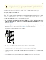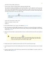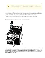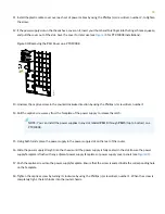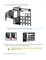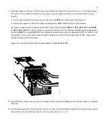
Figure 35: Removing the Power Supply Cover on a PTX10008
g100613
12. Unscrew the captive screw in the counterclockwise direction by using the Phillips (+) screwdriver, number 1.
13. Rotate the captive screw away from the faceplate of the power supply to release the latch.
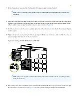
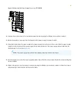
14. Using both hands, place the power supply in the power supply slot on the rear of the router. Slide the power supply
straight into the chassis until the power supply is fully seated in the slot. The power supply will protrude from the
chassis about 2 in. (5 cm) (see
NOTE:
The power supply fans will start immediately when inserted into the chassis.
15. Push the captive screw into the power supply faceplate. Ensure that the screw is seated inside the corresponding hole
on the faceplate.
16. Tighten the captive screw by turning it clockwise by using the Phillips (+) screwdriver, number 1. When the screw is
completely tight, the latch locks into the router chassis.
39


