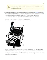
Table 3: Setting the JNP10K-PWR-DC2 Dip Switches (continued)
Field
State
Switch
Enabled for 80 A feed; 5000-W for a single feed, 5500-W for dual feeds
On
3
Enabled for 60 A feed; power supply capacity is 3000-W
Off
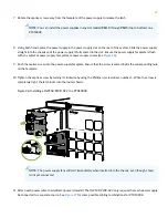
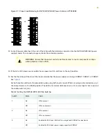
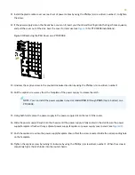
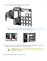
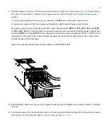
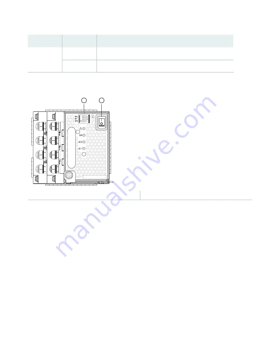
Figure 37: Setting the Enable Switches for the Power Source
g100597
1
2
2
—
1
—
Power switch, on (|) and standby (O)
Dip switches
19. Verify that the input 1 and 2 LEDs on the power supply faceplate are lit and are on steadily.
20. Press the power switch to the on (|) position.
Step 7–Connecting to the Network
You can configure and manage the PTX10008 by using a dedicated console. Every control board has a console port with
an RJ-45 connector. Use the console port to connect the device to the management console or to a console server. The
console port accepts a cable with an RJ-45 connector.
Ensure that you have an Ethernet cable with an RJ-45 connector available. An RJ-45 cable and an RJ-45 to DB-9 serial
port adapter are supplied with the device.
41

