background image

Install the Device Without a Mechanical Lift

To install the device without a mechanical lift:

Remove Components on page 10

Lift the Chassis into the Rack on page 11

Reinstall Components on page 12

Remove Components

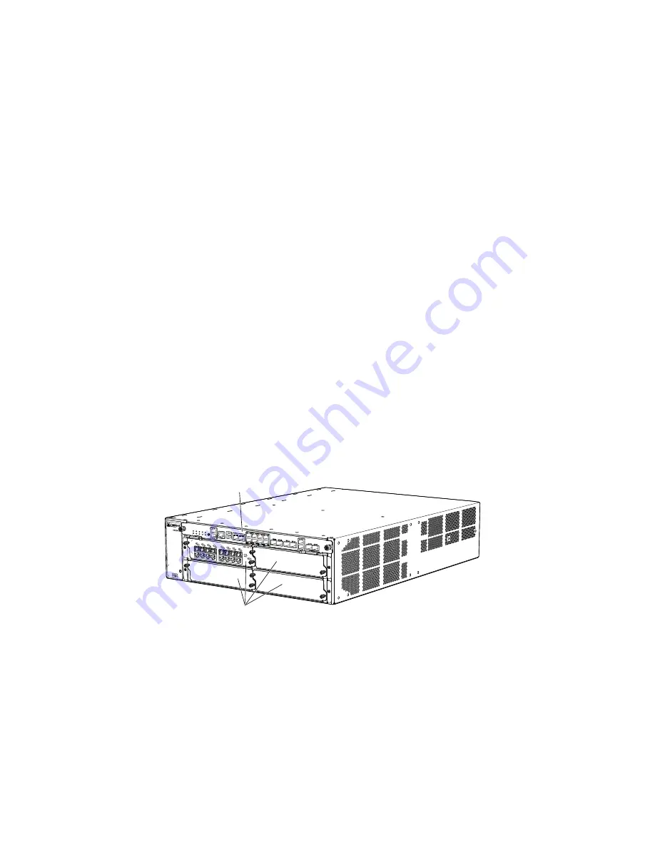
To make the services gateway light enough to install manually, you first remove most
components from the chassis as shown in Figure 9 on page 10 and
Figure 10 on page 11. The procedure in this section for removing components from
the chassis is for initial installation only and assumes that you have not connected
power cables to the services gateway:

Power supplies

Switch Fabric Board (SFB)

Routing Engine

I/O Cards (IOCs)

Network Processing Cards (NPCs)

Services Processing Cards (SPCs)

Fan tray

Figure 9: Components to Remove from the Front of the Device

0

1234

g030263

Cards in
CFM slots

SFB

10

Step 3: Install the Device

SRX 3400 Services Gateway Getting Started Guide

Summary of Contents for SRX 3400

Page 1: ...the Device Using a Lift 7 Install the Device Without a Mechanical Lift 10 Remove Components 10 Lift the Chassis into the Rack 11 Reinstall Components 12 Step 4 Connect the External Devices and IOC Cables 12 Connect to a Network for Out of Band Management 13 Connect a Management Console 13 Connect the IOC Cables 13 Step 5 Connect the Ground and Power Cables 14 Connect the Grounding Cable 14 Connect...

Page 2: ...gs 22 Compliance Statements for EMC Requirements 24 Canada 24 European Union 24 List of Technical Publications 24 Requesting Technical Support 25 Revision History 26 2 SRX 3400 Services Gateway Getting Started Guide ...

Page 3: ...ith multi processor architecture The services gateway has a capacity of up to 20 gigabits per second Gbps full duplex The device is 3 rack units U tall Sixteen devices can be stacked in a single floor to ceiling rack for increased port density per unit of floor space The device provides seven Common Form factor Module CFM slots that can be populated with up to four Services Processing Cards SPCs u...

Page 4: ...it your network Table 1 on page 4 describes the minimum system configuration for the SRX 3400 Table 1 Minimum System Configuraton Minimum Component 1 SFB 1 SPC 1 NPC 1 Routing Engine 1 Power Supply 1 Fan Tray Three types of IOC interface cards are available 16 port copper Ethernet Fast Ethernet Gigabit Ethernet 10 100 1000 Mbps card 16 port SFP Gigabit Ethernet card 2 port XFP 10 Gigabit Ethernet ...

Page 5: ... 17 5 in 44 5 cm wide The outer edges of the mounting brackets extend the width to 19 in 48 3 cm The rack must be strong enough to support the weight of the fully configured device up to 75 lbs 34 1 kg If you stack five fully configured devices in one rack it must be capable of supporting about 375 lb 170 kg For service personnel to remove and install hardware components there must be adequate spa...

Page 6: ...brackets in the accessory kit 2 Use the screws provided to secure the rack mount brackets to the sides of the chassis For a two post rack mount the brackets at the mid mount holes as shown in Figure 3 on page 6 For a four post rack mount the brackets near the front edge of the chassis as shown in Figure 4 on page 6 Figure 3 Attaching Mounting Hardware for Two Post Rack g030257 Figure 4 Attaching M...

Page 7: ...vice depends on whether you use a mechanical lift Install the Device Using a Lift on page 7 Install the Device Without a Mechanical Lift on page 10 Install the Device Using a Lift 1 Ensure the rack is in its permanent location and is secured to the building Ensure that the installation site allows adequate clearance for both airflow and maintenance For details see the SRX 3400 Services Gateway Har...

Page 8: ...binet mounting position the device so that the bottom rear edge of the chassis rests on the support shelf you installed earlier as shown in Figure 5 on page 7 4 Install a mounting screw into each of the two aligned holes as shown in Figure 7 on page 9 two post rack or Figure 8 on page 9 four post rack Use a number 2 phillips screwdriver to tighten the screws 8 Step 3 Install the Device SRX 3400 Se...

Page 9: ...ng screws in each mounting bracket 6 Move the lift away from the rack 7 Visually inspect the alignment of the device If the device is installed properly in the rack all the mounting screws on one side of the rack should be aligned with the mounting screws on the opposite side and the device should be level Step 3 Install the Device 9 Step 3 Install the Device ...

Page 10: ...igure 9 on page 10 and Figure 10 on page 11 The procedure in this section for removing components from the chassis is for initial installation only and assumes that you have not connected power cables to the services gateway Power supplies Switch Fabric Board SFB Routing Engine I O Cards IOCs Network Processing Cards NPCs Services Processing Cards SPCs Fan tray Figure 9 Components to Remove from t...

Page 11: ... as you remove it so you can reinstall it in the correct location 5 Immediately store each removed component in an antistatic bag 6 Do not stack removed components Lay each one on a flat surface NOTE For complete instructions on removing device components see Installing the Services Gateway Without a Mechanical Lift in the SRX 3400 Services Gateway Hardware Guide Lift the Chassis into the Rack Lif...

Page 12: ...rostatic discharge ESD grounding strap to your bare wrist and connect the strap to one of the ESD points on the chassis For more information about ESD see the SRX 3400 Services Gateway Hardware Guide 2 Slide each component into the chassis evenly so that it does not become stuck or damaged 3 Tighten the captive screws or lock any levers for each component installed NOTE Make sure that all empty sl...

Page 13: ...2 Plug the female DB 9 end into the device s serial port Connect the IOC Cables 1 Have ready a length of the type of cable used by the IOC For cable specifications see the SRX 3400 Services Gateway Hardware Guide 2 If you are connecting a fiber IOC cable the connector port may be covered by a rubber safety cap If it is remove the cap WARNING Do not look directly into a fiber optic transceiver or i...

Page 14: ...shipped with an AC power cord Make sure you order or obtain an AC power cord with a plug appropriate for your geographical location Connect the Grounding Cable on page 14 Connect Power to an AC Powered Services Gateway on page 15 Connect Power to a DC Powered Services Gateway on page 16 Connect the Grounding Cable 1 Attach an electrostatic discharge ESD grounding strap to your bare wrist and conne...

Page 15: ...information about ESD see the SRX 3400 Services Gateway Hardware Guide 2 Locate the power cord or cords you will use to connect the device to AC power See the SRX 3400 Services Gateway Hardware Guide for specifications 3 For each power supply a Insert the appliance coupler end of the power cord into the appliance inlet on the power supply b Insert the power cord plug into an external AC power sour...

Page 16: ...r supply is correctly installed the power supply powers up automatically If the AC power supply is installed correctly the PWR LED on the SFB lights steadily If the PWR LED indicates that the power supply is not functioning normally repeat the installation and cabling procedures Connect Power to a DC Powered Services Gateway WARNING The device must be properly grounded before you connect the DC po...

Page 17: ...active during installation 2 Attach an electrostatic discharge ESD grounding strap to your bare wrist and connect the strap to one of the ESD points on the chassis For more information about ESD see the SRX 3400 Services Gateway Hardware Guide 3 For each power supply a Remove the clear plastic cover protecting the terminal studs on the faceplate b Attach the positive DC source power cable lug to t...

Page 18: ... is available and the DC power supply is correctly installed the power supply will power up automatically If the DC power supply is installed correctly and functioning normally the PWR LED on the SFB lights steadily If the PWR LED indicates that the power supply is not functioning normally repeat the installation and cabling procedures Step 6 Perform the Initial Software Configuration This procedu...

Page 19: ...name includes spaces enclose the name in quotation marks configure edit admin set system host name host name 11 Configure the IP address and prefix length for the device s Ethernet interface edit admin set interfaces fxp0 unit 0 family inet address address prefix length 12 Configure the traffic interface edit admin set interfaces ge 0 0 0 unit 0 family inet address address prefix length admin set ...

Page 20: ...min commit commit complete 18 Optionally display the configuration to verify that it is correct admin show Last changed 2008 05 07 22 43 25 UTC version 9 2I0 builder system autoinstallation host name henbert root authentication encrypted password 1 oTVn2KY3 uQe4xzQCxpR2j7sKuV Pa0 SECRET DATA login user admin uid 928 class super user authentication encrypted password 1 cdOPmACd QvreBsJkNR1EF0uurTBk...

Page 21: ...nit 0 family inet address 192 168 10 2 24 routing options static route 0 0 0 0 0 next hop 5 1 1 2 security zones security zone trust interfaces ge 0 0 0 0 security zone untrust interfaces ge 0 0 1 0 policies from zone trust to zone untrust policy bob match source address any destination address any application any then permit Step 6 Perform the Initial Software Configuration 21 Step 6 Perform the ...

Page 22: ...able for connection to intrabuilding or unexposed wiring or cabling only The intrabuilding port s of the device MUST NOT be metallically connected to interfaces that connect to the OSP or its wiring These interfaces are designed for use as intrabuilding interfaces only Type 2 or Type 4 ports as described in GR 1089 CORE Issue 4 and require isolation from the exposed OSP cabling The addition of pri...

Page 23: ...to lift the chassis by the power supply handles The device should be mounted at the bottom of the rack if it is the only unit in the rack When mounting the device in a partially filled rack load the rack from the bottom to the top with the heaviest component at the bottom of the rack If the rack is provided with stabilizing devices install the stabilizers before mounting or servicing the device in...

Page 24: ... stateful firewall policies IPsec VPNs firewall screens Network Address Translation NAT Public Key Cryptography chassis clusters Application Layer Gateways ALGs and Intrusion Detection and Prevention IDP JUNOS Software Administration Guide Shows how to monitor SRX series and J series devices and routing operations firewall and security services system alarms and events and network performance This...

Page 25: ...urs a day 7 days a week 365 days a year Self Help Online Tools and Resources For quick and easy problem resolution Juniper Networks has designed an online self service portal called the Customer Support Center CSC that provides you with the following features Find CSC offerings http www juniper net customers support Search for known bugs http www2 juniper net kb Find product documentation http www...

Page 26: ... JUNOSe is a trademark of Juniper Networks Inc All other trademarks service marks registered trademarks or registered service marks are the property of their respective owners Juniper Networks assumes no responsibility for any inaccuracies in this document Juniper Networks reserves the right to change modify transfer or otherwise revise this publication without notice Products made or sold by Juni...

Reviews: