set security zones security-zone trust interfaces pt-1/0/0.0 host-inbound-traffic protocols
all
6.
Set security policies:
set security policies default-policy permit-all
Related
Documentation
1-Port VDSL2 Annex A Mini-Physical Interface Module (SRX-MP-1VDSL2-R) Overview
on page 25
•
•
•
1-Port VDSL2 Annex A Mini-Physical Interface Module (SRX-MP-1VDSL2-R) LEDs on
page 27
•
1-Port VDSL2 Annex A Mini-Physical Interface Module (SRX-MP-1VDSL2-R) Supported
Profiles on page 27
LTE Mini-Physical Interface Module Installation and Configuration
•
Installing the LTE Mini-PIM on page 77
•
Configuring the LTE Mini-PIM on page 80
Installing the LTE Mini-PIM
To install the LTE Mini-PIM in a services gateway:
NOTE:
You can install only one Mini-PIM in a services gateway. The Mini-PIM
can be installed in any of the Mini-PIM slots on the services gateway.
1.
Attach an electrostatic discharge (ESD) grounding strap to your bare wrist, and connect
the strap to the grounding point on the back of the services gateway.
2.
Power off the services gateway by briefly pressing the
Power
button on the front panel.
Wait for the
Power
LED to turn off before proceeding. Disconnect the services gateway
from the power source.
3.
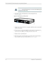
Remove the blank Mini-PIM installed on the services gateway:
a. Loosen the screws on the faceplate of the blank Mini-PIM.
b. Grasp the screws on each side and remove the blank Mini-PIM.
4.
Remove the LTE Mini-PIM from the electrostatic bag.
5.
Grasp the screws on each side of the Mini-PIM faceplate and align the notches in the
connector at the rear of the Mini-PIM with the notches in the Mini-PIM slot in the
services gateway.
77
Copyright © 2017, Juniper Networks, Inc.
Chapter 11: Configuring Mini-Physical Interface Modules


