background image

user@host# set interfaces dl0 unit 0 family inet negotiate-address

user@host# set interfaces dl0 unit 0 family inet6 negotiate-address

user@host# set interfaces dl0 unit 0 dialer-options pool

dialer-pool-number

user@host# set interfaces dl0 unit 0 dialer-options dial-string

dial-number

user@host# set interfaces

interface-name

unit 0 backup-options interface dl0.0

Related

Documentation

LTE Mini-Physical Interface Module LEDs on page 42

LTE Mini-Physical Interface Module Hardware Specifications on page 43

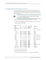
Firmware Upgrade on the LTE Mini-Physical Interface Module

Mini-PIM Firmware Upgrade Using the CLI on page 82

Modem Firmware Upgrade Through Over-the-Air (OTA) on page 84

Mini-PIM Firmware Upgrade Using the CLI

To upgrade the firmware on the Mini-PIM, using the CLI:

NOTE:

When you upgrade the firmware on the Mini-PIM, the modem firmware

is also upgraded.

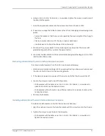
1.

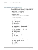
Identify the currently installed firmware version and new firmware version available
for upgrade:

user@host > show system firmware

Part             Type           Tag Current   Available Status
                                    version   version
FPC 1           
  PIC 0          MLTE_FW        1   17.2.91             OK                
Routing Engine 0 RE BIOS        0   3.2       3.2       OK                
Routing Engine 0 RE BIOS Backup 1   3.2       3.2       OK                

a. If the

Available Version

field in the output does not list any information, it indicates

that the device is not running the latest jfirmware. Proceed to Step 2 to download
and upgrade to the latest jfirmware.

b. If the

Available Version

field in the output lists the firmware version, proceed to

Step 4.

2.

Download the appropriate jfirmware version from

http://www.juniper.net/support/downloads/group/?f=junos

:

NOTE:

Ensure that the jfirmware version is the same as the version of the

Junos OS installed on the device. To know the Junos OS version, issue the

show version

command.

Copyright © 2017, Juniper Networks, Inc.

82

SRX300 Series and SRX550 High Memory Gateway Interface Modules Reference

Summary of Contents for SRX300 Series

Page 1: ...SRX300 Series and SRX550 High Memory Gateway Interface Modules Reference Modified 2017 08 14 Copyright 2017 Juniper Networks Inc ...

Page 2: ...e Modules Reference Copyright 2017 Juniper Networks Inc All rights reserved The information in this document is current as of the date on the title page YEAR 2000 NOTICE Juniper Networks hardware and software products are Year 2000 compliant Junos OS has no known time related limitations through the year 2038 However the NTP application is known to have some difficulty in the year 2036 END USER LI...

Page 3: ...rvices Gateway Interface Modules and Compatibility 7 MTU Default and Maximum Values for Physical Interface Modules 8 Power over Ethernet Support on SRX550 High Memory Services Gateway Interfaces 10 SRX300 Series and SRX550 High Memory Services Gateway Interfaces Power and Heat Requirements 12 Part 2 Interface Module Descriptions Chapter 2 1 Port Serial Mini Physical SRX MP 1SERIAL R Interface Modu...

Page 4: ...erview 35 16 Port Gigabit Ethernet XPIM PoE Components 36 16 Port Gigabit Ethernet XPIM PoE Hardware Specifications 37 16 Port Gigabit Ethernet XPIM PoE LEDs 37 Chapter 7 LTE Mini Physical Interface Module 39 LTE Mini Physical Interface Module 39 LTE Mini Physical Interface Module LEDs 42 LTE Mini Physical Interface Module Hardware Specifications 43 Part 3 Cable Specifications and Pinouts Chapter ...

Page 5: ...sing the CLI 72 1 Port T1 E1 Mini Physical Interface Module SRX MP 1T1E1 R Basic Configuration 73 Using the J Web Interface 73 Using the CLI 74 1 Port VDSL2 Annex A Mini Physical Interface Module SRX MP 1VDSL2 R Basic Configuration 75 Using the J Web Interface 75 Using the CLI 76 LTE Mini Physical Interface Module Installation and Configuration 77 Installing the LTE Mini PIM 77 Configuring the LTE...

Page 6: ...Gigabit Backplane Physical Interface Module Faceplate 102 Installing a Blank Gigabit Backplane Physical Interface Module Faceplate 102 Chapter 16 Contacting Customer Support and Returning Components 105 Contacting Customer Support 105 Return Procedure for SRX Series Services Gateway Hardware Components 106 Locating the SRX Series Services Gateway Hardware Component Mini PIM or GPIM Serial Number L...

Page 7: ...face Module 25 Figure 6 VDSL2 Annex A SRX MP 1VDSL2 R Mini PIM 25 Chapter 5 8 Port Gigabit Ethernet SFP XPIM 29 Figure 7 8 Port Gigabit Ethernet SFP XPIM Front Panel 29 Chapter 6 16 Port Gigabit Ethernet XPIM PoE 35 Figure 8 16 Port Gigabit Ethernet with PoE XPIM 36 Chapter 7 LTE Mini Physical Interface Module 39 Figure 9 LTE Mini PIM Front Panel 39 Figure 10 LTE Mini PIM LEDs 42 Part 3 Cable Spec...

Page 8: ...ules Chapter 13 Overview of Replacing Interface Modules 93 Figure 16 Placing a Component into an Electrostatic Bag 94 Copyright 2017 Juniper Networks Inc viii SRX300 Series and SRX550 High Memory Gateway Interface Modules Reference ...

Page 9: ...Part 2 Interface Module Descriptions Chapter 2 1 Port Serial Mini Physical SRX MP 1SERIAL R Interface Module 15 Table 13 1 Port Serial Mini PIM SRX MP 1SERIAL R Physical Specifications 16 Table 14 1 Port Serial Mini PIM SRX MP 1SERIAL R LED States 17 Chapter 3 1 Port T1 E1 Mini Physical SRX MP 1T1E1 R Interface Module 19 Table 15 1 Port T1 E1 Mini PIM SRX MP 1T1E1 R Physical Specifications 20 Tabl...

Page 10: ...VDSL2 Mini Physical Interface Module Cable Specifications 51 Table 39 RJ 11 Cable Pinout Details for 1 Port VDSL2 Annex A SRX MP 1VDSL2 R Mini PIM 52 Chapter 10 Serial Mini Physical Interface Module Cable Specifications 53 Table 40 Juniper Networks Serial Cables 53 Table 41 EIA 530A DCE Cable Pinouts for the 1 Port Serial Mini PIM 55 Table 42 EIA 530A DTE Cable Pinouts for the 1 Port Serial Mini P...

Page 11: ...Table 53 Return Procedure for SRX Series Services Gateways Component 106 xi Copyright 2017 Juniper Networks Inc List of Tables ...

Page 12: ...Copyright 2017 Juniper Networks Inc xii SRX300 Series and SRX550 High Memory Gateway Interface Modules Reference ...

Page 13: ...in the latest release notes differs from the information in the documentation follow the product Release Notes Juniper Networks Books publishes books by Juniper Networks engineers and subject matter experts These books go beyond the technical documentation to explore the nuances of network architecture deployment and administration The current list can be viewed at http www juniper net books Suppo...

Page 14: ...figure command user host configure Represents text that you type Bold text like this user host show chassis alarms No alarms currently active Represents output that appears on the terminal screen Fixed width text like this A policy term is a named structure that defines match conditions and actions Junos OS CLI User Guide RFC 1997 BGP Communities Attribute Introduces or emphasizes important new te...

Page 15: ...re brackets edit routing options static route default nexthop address retain Identifies a level in the configuration hierarchy Indention and braces Identifies a leaf statement at a configuration hierarchy level semicolon GUI Conventions In the Logical Interfaces box select All Interfaces To cancel the configuration click Cancel Represents graphical user interface GUI items you click or select Bold...

Page 16: ...ce portal called the Customer Support Center CSC that provides you with the following features Find CSC offerings http www juniper net customers support Search for known bugs http www2 juniper net kb Find product documentation http www juniper net techpubs Find solutions and answer questions using our Knowledge Base http kb juniper net Download the latest versions of software and review release no...

Page 17: ...For international or direct dial options in countries without toll free numbers see http www juniper net support requesting support html xvii Copyright 2017 Juniper Networks Inc About the Documentation ...

Page 18: ...Copyright 2017 Juniper Networks Inc xviii SRX300 Series and SRX550 High Memory Gateway Interface Modules Reference ...

Page 19: ...PART 1 Overview SRX Series Services Gateway Interface Modules Support on page 3 1 Copyright 2017 Juniper Networks Inc ...

Page 20: ...Copyright 2017 Juniper Networks Inc 2 SRX300 Series and SRX550 High Memory Gateway Interface Modules Reference ...

Page 21: ...at Requirements on page 12 SRX300 Series and SRX550 High Memory Services Gateway Interface Overview Mini Physical Interface Modules Mini PIMs and Gigabit Backplane Physical Interface Modules GPIMs are field replaceable network interface cards NICs which provide physical connections to a LAN or a WAN You can easily insert or remove Mini PIMs and GPIMs from the front slots of the services gateway ch...

Page 22: ...ical Interface Modules on page 8 SRX300 Series and SRX550 High Memory Services Gateway Interfaces Power and Heat Requirements on page 12 SRX300 Series and SRX550 High Memory Services Gateway Gigabit Backplane Physical Interface Modules Overview A Gigabit Backplane Physical Interface Module GPIM is a network interface card NIC that installs in the front slots of the SRX550 High Memory Services Gate...

Page 23: ...emory Services Gateway GPIM XPIM Model Numbers Model Number GPIM or XPIM SRX GP 8SFP 8 Port Gigabit Ethernet SFP XPIM SRX GP 16GE POE 16 Port Gigabit Ethernet XPIM with PoE Figure 1 on page 5 shows how the slots on the front panel of the SRX550 High Memory Services Gateway are numbered Slots 1 and 2 are for Mini PIMs and slots 3 through 8 are for GPIMs Figure 1 SRX550 High Memory Services Gateway ...

Page 24: ...ou must know the slot and port number assigned to the Mini PIM or GPIM The slot number identifies the slot on the services gateway in which you insert the Mini PIM or GPIM and is typically named 1 2 3 and so on The port number is the port on the Mini PIM or GPIM that is being configured The name of each network interface has the following format to identify the physical device that corresponds to ...

Page 25: ...IM which uses 2 slots you must install it in the 10 Gigabit or 20 Gigabit GPIM slots SRX550 High Memory Services Gateway Slots 3 and 6 which refer to the right side bottom two standard slots slots 3 and 4 and the right side top two standard slots 6 and 8 16 Port Gigabit Ethernet XPIM Related Documentation SRX300 Series and SRX550 High Memory Services Gateway Mini Physical Interface Modules Overvie...

Page 26: ... Gigabit Backplane Physical Interface Modules XPIMs along with the SRX Series devices and the Junos OS releases that support them Table 7 XPIM Types and Hardware Platform Compatibility First Junos OS Release Name Type SRX550 High Memory SRX300 Series Services Gateways Junos OS Release 15 1X49 D30 Not supported 8 Port Gigabit Ethernet SFP XPIMs 10 Gigabit Ethernet GPIM Junos OS Release 15 1X49 D30 ...

Page 27: ...ize measured in bytes of the largest physical packet that a network can transmit Any message larger than the MTU is divided into smaller packets before it is sent to its final destination Maximum MTU Table 9 on page 9 lists the MTU values for the SRX300 Series and SRX550 High Memory Services Gateway Physical Interface Modules PIMs Table 9 MTU Values for the SRX300 Series and SRX550 High Memory PIM...

Page 28: ...t Backplane Physical Interface Modules Overview on page 4 Interfaces Port Naming Conventions for the SRX300 Series and SRX550 High Memory Services Gateways on page 6 SRX300 Series and SRX550 High Memory Services Gateway Interfaces Power and Heat Requirements on page 12 Power over Ethernet Support on SRX550 High Memory Services Gateway Interfaces Power over Ethernet PoE supports the implementation ...

Page 29: ...oE is supported on the front panel slots 3 4 6 and 8 Supported slots ports The 645 W AC and 645 W DC power supplies support the following capacities 255 W PoE on a single power supply or with redundancy using the two power supply option 510 W PoE using the two power supply option operating as nonredundant Total PoE power sourcing capacity 31 2 W Per port power limit Static Power allocation for eac...

Page 30: ...el 4 29 Serial Mini PIM 1 92 T1 E1 Mini PIM 9 80 VDSL2 Mini PIM 22 8 Port Gigabit Ethernet SFP XPIM 40 without PoE 16 Port Gigabit Ethernet XPIM 4 8 LTE Mini PIM Related Documentation MTU Default and Maximum Values for Physical Interface Modules on page 8 Power over Ethernet Support on SRX550 High Memory Services Gateway Interfaces on page 10 Copyright 2017 Juniper Networks Inc 12 SRX300 Series an...

Page 31: ...15 1 Port T1 E1 Mini Physical SRX MP 1T1E1 R Interface Module on page 19 1 Port VDSL2 Annex A Mini Physical Interface Module on page 25 8 Port Gigabit Ethernet SFP XPIM on page 29 16 Port Gigabit Ethernet XPIM PoE on page 35 LTE Mini Physical Interface Module on page 39 13 Copyright 2017 Juniper Networks Inc ...

Page 32: ...Copyright 2017 Juniper Networks Inc 14 SRX300 Series and SRX550 High Memory Gateway Interface Modules Reference ...

Page 33: ...taining and terminating a connection A modem is a typical DCE device A serial cable connects the DCE to a telephony network where ultimately a link is established with data terminal equipment DTE DTE is typically where a link terminates Figure 4 on page 15 shows the front panel of the 1 Port Serial Mini Physical Interface Module Mini PIM Figure 4 1 Port Serial Mini PIM SRX MP 1SERIAL R Front Panel...

Page 34: ...l Mini PIM SRX MP 1SERIAL R Physical Specifications Value Description 0 8 in x 3 75 in x 5 9 in 2 0 cm x 9 5 cm x 14 5 cm Dimensions H x W x L 3 04 oz 86 g Weight 60 pin Synchronous Serial female Connector type Mini PIM Form factor Related Documentation 1 Port Serial Mini Physical Interface Module SRX MP 1SERIAL R Overview on page 15 1 Port Serial Mini Physical Interface Module SRX MP 1SERIAL R LE...

Page 35: ...vice has detected a failure Off Related Documentation 1 Port Serial Mini Physical Interface Module SRX MP 1SERIAL R Overview on page 15 1 Port Serial Mini Physical Interface Module SRX MP 1SERIAL R Hardware Specifications on page 16 17 Copyright 2017 Juniper Networks Inc Chapter 2 1 Port Serial Mini Physical SRX MP 1SERIAL R Interface Module ...

Page 36: ...Copyright 2017 Juniper Networks Inc 18 SRX300 Series and SRX550 High Memory Gateway Interface Modules Reference ...

Page 37: ...ons on page 22 1 Port T1 E1 Mini Physical Interface Module SRX MP 1T1E1 R Overview The 1 Port T1 E1 Mini Physical Interface Module Mini PIM provides the physical connection to T1 or E1 network media types and also performs T1 or E1 framing and line speed signaling Figure 5 on page 19 shows the front panel of the 1 Port T1 E1 Mini PIM SRX MP 1T1E1 R Figure 5 1 Port T1 E1 Mini Physical Interface Mod...

Page 38: ...ted Loopback Diagnostics on page 21 1 Port T1 E1 Mini Physical Interface Module SRX MP 1T1E1 R Network Interface Specifications on page 22 1 PortT1 E1Mini PhysicalInterfaceModule SRX MP 1T1E1 R HardwareSpecifications Table 15 on page 20 gives the physical specifications of the 1 Port T1 E1 Mini Physical Interface Module Mini PIM Table 15 1 Port T1 E1 Mini PIM SRX MP 1T1E1 R Physical Specifications...

Page 39: ... is not active Off Indicates that the Mini PIM link is up On Green CD Carrier Detector Indicates that carrier detect is not active Off Related Documentation 1 Port T1 E1 Mini Physical Interface Module SRX MP 1T1E1 R Overview on page 19 1 Port T1 E1 Mini Physical Interface Module SRX MP 1T1E1 R Hardware Specifications on page 20 1 Port T1 E1 Mini Physical Interface Module SRX MP 1T1E1 R Supported L...

Page 40: ... 1 Port T1 E1 Mini Physical Interface Module SRX MP 1T1E1 R LEDs on page 21 1 Port T1 E1 Mini Physical Interface Module SRX MP 1T1E1 R Network Interface Specifications The 1 Port T1 E1 Mini Physical Interface Module Mini PIM has the network interface specifications given in Table 17 on page 22 Table 17 1 Port T1 E1 Mini PIM SRX MP 1T1E1 R Network Interface Specifications E1 Specifications T1 Speci...

Page 41: ...r Align Error Runts Giants FCS Error Abort Error Align Error Counters Related Documentation 1 Port T1 E1 Mini Physical Interface Module SRX MP 1T1E1 R Overview on page 19 1 Port T1 E1 Mini Physical Interface Module SRX MP 1T1E1 R Hardware Specifications on page 20 1 Port T1 E1 Mini Physical Interface Module SRX MP 1T1E1 R LEDs on page 21 1 Port T1 E1 Mini Physical Interface Module SRX MP 1T1E1 R S...

Page 42: ...Copyright 2017 Juniper Networks Inc 24 SRX300 Series and SRX550 High Memory Gateway Interface Modules Reference ...

Page 43: ... rate digital subscriber line VDSL technology is part of the xDSL family of modem technologies which provide faster data transmission over a single flat untwisted or twisted pair of copper wires The 1 Port VDSL2 Annex A Mini PIM carries the Ethernet backplane When the Mini PIM is plugged into the chassis the Mini PIM connects to one of the ports of the baseboard switch The 1 Port VDSL2 Annex A Min...

Page 44: ...sical Interface Module SRX MP 1VDSL2 R Hardware Specifications on page 26 1 Port VDSL2 Annex A Mini Physical Interface Module SRX MP 1VDSL2 R LEDs on page 27 1 Port VDSL2 Annex A Mini Physical Interface Module SRX MP 1VDSL2 R Supported Profiles on page 27 1 Port VDSL2 Annex A Mini Physical Interface Module SRX MP 1VDSL2 R Hardware Specifications Table 18 on page 26 gives the hardware specification...

Page 45: ...is trained On Green SYNC Indicates training is in progress Blinking Indicates that traffic is passing through Blinking Green TX RX Indicates that no traffic is passing through Off Related Documentation 1 Port VDSL2 Annex A Mini Physical Interface Module SRX MP 1VDSL2 R Overview on page 25 1 Port VDSL2 Annex A Mini Physical Interface Module SRX MP 1VDSL2 R Hardware Specifications on page 26 1 Port ...

Page 46: ...on 1 Port VDSL2 Annex A Mini Physical Interface Module SRX MP 1VDSL2 R Overview on page 25 1 Port VDSL2 Annex A Mini Physical Interface Module SRX MP 1VDSL2 R Hardware Specifications on page 26 1 Port VDSL2 Annex A Mini Physical Interface Module SRX MP 1VDSL2 R LEDs on page 27 Copyright 2017 Juniper Networks Inc 28 SRX300 Series and SRX550 High Memory Gateway Interface Modules Reference ...

Page 47: ...nd system processor dependent Layer 3 service with connection of up to eight SFP Gigabit Ethernet ports The 8 Port Gigabit Ethernet SFP XPIM complements the on board 10 100 1000 Mbps Ethernet interfaces with extended WAN connectivity It supports a variety of transceivers This XPIM can be used in copper and optical environments to provide maximum flexibility when upgrading from an existing infrastr...

Page 48: ...ort Gigabit Ethernet SFP XPIM Components The 8 Port Gigabit Ethernet small form factor pluggable Gigabit Backplane Physical Interface Module SFP XPIM contains the components listed in Table 21 on page 30 Table 21 8 Port Gigabit Ethernet SFP XPIM Components Description Location Component Use the ONLINE OFFLINE button to gracefully shut down the XPIM Press and hold the button for 4 to 5 seconds and ...

Page 49: ...erature 5 to 90 noncondensing Relative humidity Up to 10 000 ft 3000 m Altitude Related Documentation 8 Port Gigabit Ethernet SFP XPIM Overview on page 29 8 Port Gigabit Ethernet SFP XPIM Components on page 30 8 Port Gigabit Ethernet SFP XPIM LEDs on page 31 8 Port Gigabit Ethernet SFP XPIM Supported Transceivers on page 32 8 Port Gigabit Ethernet SFP XPIM Network Interface Specifications on page ...

Page 50: ...pecifications on page 31 8 Port Gigabit Ethernet SFP XPIM Supported Transceivers on page 32 8 Port Gigabit Ethernet SFP XPIM Network Interface Specifications on page 34 8 Port Gigabit Ethernet SFP XPIM Supported Transceivers You can customize the Ethernet interface type by using different 1 port small form factor pluggable SFP transceivers Table 24 on page 32 lists the SFP transceivers and cables ...

Page 51: ...0 km TX 1310 nm 1550 nm EX SFP GE40KT13R15 LC 1000BASE BX at 40 km TX1550 nm RX1310 nm EX SFP GE40KT15R13 CAUTION If you face a problem running a Juniper Networks device that uses a third party optic or cable the Juniper Networks Technical Assistance Center JTAC can help you diagnose the source of the problem Your JTAC engineer mightrecommendthatyoucheckthethird partyopticorcableandpotentially rep...

Page 52: ...Q virtual LANs VLAN support Supported Class of service support DIX LLC SNAP CCC TCC and VLAN CCC Encapsulations Supported Loopback diagnostic feature Supported Autonegotiation Related Documentation 8 Port Gigabit Ethernet SFP XPIM Overview on page 29 8 Port Gigabit Ethernet SFP XPIM Components on page 30 8 Port Gigabit Ethernet SFP XPIM Hardware Specifications on page 31 8 Port Gigabit Ethernet SF...

Page 53: ...ices Gateway supports the PoE model The PoE GPIMs provide ports that supply electric power over the same ports that are used to connect network devices For more information about PoE see Power over Ethernet Support on SRX550 High Memory Services Gateway Interfaces on page 10 The 16 Port Gigabit Ethernet XPIM must be installed in one of the following 20 Gigabit slots on the SRX550 High Memory Servi...

Page 54: ...6 Port Gigabit Ethernet XPIM PoE Components The 16 Port Gigabit Ethernet XPIM contains the components listed in Table 26 on page 36 Table 26 16 Port Gigabit Ethernet XPIM Components Description Location Component Use the XPIM ONLINE OFFLINE button to gracefully shut down the XPIM Right side of the XPIM XPIMONLINE OFFLINEbutton The SRX550 High Memory Services Gateway does not support hot swappable ...

Page 55: ...rnet XPIM Hardware Specifications Value Description 1 58 in x 6 72 in x 8 5 in 4 0 cm x 17 1 cm x 21 6 cm Dimensions H x W x L 16 5 oz 0 68 kg Weight 16 RJ 45 Connector type Double high single wide XPIM Form factor 32 F through 104 F 0 C through 40 C Environmental operating temperature 40 F through 158 F 40 C through 70 C Storage temperature 5 to 90 noncondensing Relative humidity Related Document...

Page 56: ... sending data Blinking Not used on the non PoE XPIM N A N A N A Port is PoE enabled and online On Green PoE Port is offline Off Port is PoE enabled and receiving or sending data Blinking Related Documentation 16 Port Gigabit Ethernet XPIM PoE Overview on page 35 16 Port Gigabit Ethernet XPIM PoE Components on page 36 16 Port Gigabit Ethernet XPIM PoE Hardware Specifications on page 37 Copyright 20...

Page 57: ...works The Mini PIM supports up to two SIM cards and can be installed in any of the Mini PIM slots on the services gateways The Mini PIM supports the following features Automatic switchover between service providers through dual SIMs Storage support for multiple service provider and access point name APN profiles LTE carrier aggregation SIM lock and unlock capability Always on dial on demand and ba...

Page 58: ... antennas which can be rotated 360 You can rotate the antennas and select the angle at which the signal strength is high Table 30 on page 40 lists the specifications for the antenna Table 30 Specifications for the LTE Mini PIM Antenna Value Specification EDA 2010 4G0R2 A2 Vendor MAG LAYERS Part number 704 960 MHz 1710 2700 MHz Operating frequency range 5 maximum Voltage Standing Wave Ratio VSWR 50...

Page 59: ...40 and 41 For 3G HSPA Bands 1 5 6 8 9 and 19 Asia Australia LTE HSPA SRX MP LTE AA The Mini PIM can be configured in three modes Always on The Mini PIM connects to the 3G 4G network after booting The connection is always maintained as long as there are no network or connectivity problems Dial on demand The Mini PIM initiates a connection when it receives traffic Backup The Mini PIM connects to the...

Page 60: ...M LEDs g009650 Table 33 on page 42 lists the LEDs on the LTE Mini PIM and their indications Table 33 LTE Mini PIM LED States Description LED Solid green one bar Low signal strength 99 dBm SIG Received Signal Strength Indicator Solid green two bars Low signal strength from 98 dBm to 87 dBm Solid green three bars Low signal strength from 86 dBm to 76 dBm Solid green four bars High signal strength 75...

Page 61: ...e Module Hardware Specifications Table 34 on page 43 provides the hardware specifications for the LTE Mini PIM Table 34 LTE Mini PIM Hardware Specifications Value Description 0 80 in x 3 75 in x 5 9 in 2 0 cm x 9 5 cm x 14 5 cm Dimensions H x W x L 0 23 lb 0 106 kg Weight SMA Connector type Mini PIM Form factor 32 F through 104 F 0 C through 40 C Environmental operating temperature 40 F through 15...

Page 62: ...Copyright 2017 Juniper Networks Inc 44 SRX300 Series and SRX550 High Memory Gateway Interface Modules Reference ...

Page 63: ...Pinouts T1 E1 Mini Physical Interface Module on page 47 VDSL2 Mini Physical Interface Module Cable Specifications on page 51 Serial Mini Physical Interface Module Cable Specifications on page 53 45 Copyright 2017 Juniper Networks Inc ...

Page 64: ...Copyright 2017 Juniper Networks Inc 46 SRX300 Series and SRX550 High Memory Gateway Interface Modules Reference ...
Page 65: ...1 Port T1 E1 Mini Physical Interface Module Mini PIM uses an RJ 48 cable which is not supplied with the Mini PIM CAUTION To maintain agency approvals use only a properly constructed shielded cable Table 35 on page 47 lists the RJ 48 connector to RJ 48 connector straight pinouts Table 35 RJ 48 Connector to RJ 48 Connector Straight Pinouts Signal RJ 48 Pin Data Numbering Form RJ 48 Pin on 1 Port T1 ...

Page 66: ...ctor to DB 15 Connector Pinouts for the 1 Port T1 E1 Mini Physical Interface Module SRX MP 1T1E1 R on page 48 RJ 48ConnectortoDB 15ConnectorPinoutsforthe1 PortT1 E1Mini PhysicalInterface Module SRX MP 1T1E1 R Table 37 on page 48 lists the RJ 48 connector to DB 15 connector straight pinouts Table 37 RJ 48 Connector to DB 15 Connector Straight Pinouts Signal DB 15 Pin Data Numbering Form RJ 48 Pin o...

Page 67: ...e 38 on page 49 lists the RJ 48 connector to DB 15 connector crossover pinouts Table 38 RJ 48 Connector to DB 15 Connector Crossover Pinouts Signal DB 15 Pin Data Numbering Form RJ 48 Pin on T1 E1 Mini PIM RX Ring TX Ring 9 1 RX Tip TX Tip 1 2 TX Ring RX Ring 11 4 TX Tip RX Tip 3 5 Shield Return Ground 4 3 Shield Return Ground 2 6 No connect No connect 7 No connect No connect 8 No connect No conne...

Page 68: ...ct No connect 12 No connect No connect 13 No connect No connect 14 No connect No connect 15 Related Documentation RJ 48 Connector to RJ 48 Connector Pinouts for the 1 Port T1 E1 Mini Physical Interface Module SRX MP 1T1E1 R on page 47 Copyright 2017 Juniper Networks Inc 50 SRX300 Series and SRX550 High Memory Gateway Interface Modules Reference ...

Page 69: ... MP 1VDSL2 R Mini Physical Interface Module Cable Specifications The 1 Port VDSL2 Annex A Mini Physical Interface Module Mini PIM requires a standard RJ 11 cable Figure 11 on page 51 shows the RJ 11 cable design Figure 11 RJ 11 Cable Pinout for 1 Port VDSL2 Annex A SRX MP 1VDSL2 R Mini PIM Table 39 on page 52 shows the pin assignments of the RJ 11 cable 51 Copyright 2017 Juniper Networks Inc ...

Page 70: ...RX MP 1VDSL2 R Overview on page 25 1 Port VDSL2 Annex A Mini Physical Interface Module SRX MP 1VDSL2 R Hardware Specifications on page 26 1 Port VDSL2 Annex A Mini Physical Interface Module SRX MP 1VDSL2 R LEDs on page 27 1 Port VDSL2 Annex A Mini Physical Interface Module SRX MP 1VDSL2 R Supported Profiles on page 27 Copyright 2017 Juniper Networks Inc 52 SRX300 Series and SRX550 High Memory Gate...

Page 71: ...ule on page 61 V 35 DCE Cable Pinouts for the 1 Port Serial Mini Physical Interface Module on page 63 V 35 DTE Cable Pinouts for the 1 Port Serial Mini Physical Interface Module on page 64 X 21 DCE Cable Pinouts for the 1 Port Serial Mini Physical Interface Module on page 65 X 21 DTE Cable Pinouts for the 1 Port Serial Mini Physical Interface Module on page 66 1 Port Serial Mini Physical Interface...

Page 72: ... DCE Cable Pinouts for the 1 Port Serial Mini Physical Interface Module on page 57 RS 232 DTE Cable Pinouts for the 1 Port Serial Mini Physical Interface Module on page 58 RS 422 449 EIA 449 DCE Cable Pinouts for the 1 Port Serial Mini Physical Interface Module on page 59 RS 422 449 EIA 449 DTE Cable Pinouts for the 1 Port Serial Mini Physical Interface Module on page 61 V 35 DCE Cable Pinouts for...

Page 73: ...etector A 14 8 13 Receive Clock B 52 9 51 Received Line Signal Detector B 13 10 14 Terminal Timing B 5 11 6 Transmit Clock B 56 12 55 Clear to Send B 48 13 47 Transmit Data B 1 14 2 Transmit Clock A 55 15 56 Receive Data B 60 16 59 Receive Clock A 51 17 52 Local Loopback 18 45 Request to Send B 37 19 38 Data Terminal Ready A 20 9 Signal Ground 23 4 Terminal Timing A 6 24 5 26 to 25 55 Copyright 20...

Page 74: ...rface Module on page 65 EIA 530A DTE Cable Pinouts for the 1 Port Serial Mini Physical Interface Module Table 42 on page 56 gives the EIA 530A DTE cable pinouts Table 42 EIA 530A DTE Cable Pinouts for the 1 Port Serial Mini PIM Description LFH 60 Pairing DB 25 Pin LFH 60 Pin Shield Ground 1 15 Transmit Data A 59 2 60 Receive Data A 2 3 1 Request to Send A 47 4 48 Clear to Send A 38 5 37 Data Set R...

Page 75: ...tation RS 232 DTE Cable Pinouts for the 1 Port Serial Mini Physical Interface Module on page 58 RS 422 449 EIA 449 DTE Cable Pinouts for the 1 Port Serial Mini Physical Interface Module on page 61 V 35 DTE Cable Pinouts for the 1 Port Serial Mini Physical Interface Module on page 64 X 21 DTE Cable Pinouts for the 1 Port Serial Mini Physical Interface Module on page 66 RS 232 DCE Cable Pinouts for ...

Page 76: ...EIA 530A DCE Cable Pinouts for the 1 Port Serial Mini Physical Interface Module on page 54 RS 422 449 EIA 449 DCE Cable Pinouts for the 1 Port Serial Mini Physical Interface Module on page 59 V 35 DCE Cable Pinouts for the 1 Port Serial Mini Physical Interface Module on page 63 X 21 DCE Cable Pinouts for the 1 Port Serial Mini Physical Interface Module on page 65 RS 232 DTE Cable Pinouts for the 1...

Page 77: ...A 530A DTE Cable Pinouts for the 1 Port Serial Mini Physical Interface Module on page 56 RS 422 449 EIA 449 DTE Cable Pinouts for the 1 Port Serial Mini Physical Interface Module on page 61 V 35 DTE Cable Pinouts for the 1 Port Serial Mini Physical Interface Module on page 64 X 21 DTE Cable Pinouts for the 1 Port Serial Mini Physical Interface Module on page 66 RS 422 449 EIA 449 DCE Cable Pinouts...

Page 78: ...ocal Loopback 10 45 Data Mode A 34 11 33 Terminal Ready A 10 12 9 Receive Ready A 14 13 13 Terminal Timing A 6 17 5 Signal Ground 19 36 Receive Common 20 4 Send Data B 1 22 2 Send Timing B 56 23 55 Receive Data B 60 24 59 Request to Send B 37 25 38 Receive Timing B 52 26 51 Clear to Send B 48 27 47 Data Mode B 33 29 34 Terminal Ready B 9 30 10 Receiver Ready B 13 31 14 Copyright 2017 Juniper Netwo...

Page 79: ...E Cable Pinouts for the 1 Port Serial Mini Physical Interface Module on page 65 RS 422 449 EIA 449 DTE Cable Pinouts for the 1 Port Serial Mini Physical Interface Module Table 46 on page 61 gives the RS 422 449 DTE cable pinouts Table 46 RS 422 449 DTE Cable Pinouts for the 1 Port Serial Mini PIM Description LFH 60 Pairing DC 37 DB 37 Pin LFH 60 Pin Shield Ground 1 15 Send Data A 59 4 60 Send Timi...

Page 80: ...l Ready B 33 30 34 Receiver Ready B 13 31 14 Terminal Timing B 52 35 51 Send Common 37 57 26 to 25 18 to 17 Related Documentation EIA 530A DTE Cable Pinouts for the 1 Port Serial Mini Physical Interface Module on page 56 RS 232 DTE Cable Pinouts for the 1 Port Serial Mini Physical Interface Module on page 58 V 35 DTE Cable Pinouts for the 1 Port Serial Mini Physical Interface Module on page 64 X 2...

Page 81: ...end C 37 Clear to Send D 48 Data Set Ready E 33 Received Line Signal Detector F 13 Data Terminal Ready H 9 Test Mode K 45 Transmit Data A 2 P 1 Receive Data A 59 R 60 Transmit Data B 1 S 2 Receive Data B 60 T 59 Terminal Timing A 6 U 5 Receive Timing A 51 V 52 Terminal Timing B 5 W 6 Receive Timing B 52 X 51 Transmit Timing A 55 Y 56 Transmit Timing B 56 AA 55 22 to 21 26 to 25 63 Copyright 2017 J...

Page 82: ... Physical Interface Module Table 48 on page 64 describes the V 35 DTE cable pinouts Table 48 V 35 DTE Cable Pinouts for the 1 Port Serial Mini PIM Description LFH 60 Pairing M 34 Pin LFH 60 Pin Frame Ground A 15 Signal Ground B 57 Request to Send C 48 Clear to Send D 37 Data Set Ready E 9 Received Line Signal Detector F 13 Data Terminal Ready H 33 Test Mode K 41 Transmit Data A 59 P 60 Receive Dat...

Page 83: ...on page 58 X 21 DTE Cable Pinouts for the 1 Port Serial Mini Physical Interface Module on page 66 X 21 DCE Cable Pinouts for the 1 Port Serial Mini Physical Interface Module Table 49 on page 65 gives the X 21 DCE cable pinouts Table 49 X 21 DCE Cable Pinouts for the 1 Port Serial Mini PIM Description LFH 60 Pairing DB 15 Pin LFH 60 Pin Shield Ground 1 15 Transmit Data A 2 2 1 Control A 38 3 37 Rec...

Page 84: ...al Mini Physical Interface Module on page 64 X 21 DTE Cable Pinouts for the 1 Port Serial Mini Physical Interface Module on page 66 X 21 DTE Cable Pinouts for the 1 Port Serial Mini Physical Interface Module Table 50 on page 66 gives the X 21 DTE cable pinouts Table 50 X 21 DTE Cable Pinouts for the 1 Port Serial Mini PIM Description LFH 60Pairing DB 15 Pin LFH 60 Pin Shield Ground 1 15 Transmit D...

Page 85: ...or the 1 Port Serial Mini Physical Interface Module on page 56 RS 232 DTE Cable Pinouts for the 1 Port Serial Mini Physical Interface Module on page 58 RS 422 449 EIA 449 DTE Cable Pinouts for the 1 Port Serial Mini Physical Interface Module on page 61 V 35 DTE Cable Pinouts for the 1 Port Serial Mini Physical Interface Module on page 64 67 Copyright 2017 Juniper Networks Inc Chapter 10 Serial Min...

Page 86: ...Copyright 2017 Juniper Networks Inc 68 SRX300 Series and SRX550 High Memory Gateway Interface Modules Reference ...

Page 87: ...PART 4 Configuration Configuring Mini Physical Interface Modules on page 71 Configuring Gigabit Backplane Physical Interface Modules on page 87 69 Copyright 2017 Juniper Networks Inc ...

Page 88: ...Copyright 2017 Juniper Networks Inc 70 SRX300 Series and SRX550 High Memory Gateway Interface Modules Reference ...

Page 89: ... settings for the PIM You can perform the configuration tasks for this using either the J Web interface or the CLI Using the J Web Interface on page 71 Using the CLI on page 72 Using the J Web Interface To perform basic configuration of the 1 Port Serial Mini PIM and to configure network interfaces for the services gateway using the J Web interface 1 In the J Web interface select Configure Interfa...

Page 90: ... changes and select Commit Commit to apply the configuration and other pending changes if any Using the CLI To perform basic configuration for the 1 Port Serial Mini PIM and to configure network interfaces for the services gateway with the CLI 1 Verify that the serial interface is installed on the device show chassis hardware 2 Verify the status of the interface show interfaces terse 3 Assign the ...

Page 91: ...o perform basic configuration for the 1 Port T1 E1 Mini Physical Interface Module SRX MP 1T1E1 R and to configure network interfaces for the services gateway using the J Web interface 1 In the J Web interface select Configure Interfaces The Interfaces page displays and lists the network interfaces present on the services gateway along with configuration information if configured 2 Select the inter...

Page 92: ... the T1 E1 interface is installed on the device show chassis hardware 2 Verify the status of the interface show interfaces terse 3 Assign the port an IP address For T1 interfaces set interfaces t1 1 0 0 unit 0 family inet address interface address destination prefix For E1 interfaces set interfaces e1 1 0 0 unit 0 family inet address interface address destination prefix 4 Add or select a security ...

Page 93: ...face Module Mini PIM installed on the services gateway you must configure the basic settings for the PIM You can perform the configuration tasks for this using either the J Web interface or the CLI Using the J Web Interface on page 75 Using the CLI on page 76 Using the J Web Interface To perform basic configuration for the 1 Port VDSL2 Annex A Mini Physical Interface Module Mini PIM and to configu...

Page 94: ...uration and other pending changes if any For more information in the J Web interface select Configure Interfaces and click Help Using the CLI To perform basic configuration of the 1 Port VDSL2 Annex A Mini PIM and to configure network interfaces for the services gateway with the CLI 1 Verify that the 1 Port VDSL2 interface is installed on the device show chassis hardware 2 Verify the status of the...

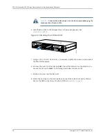
Page 95: ...tall only one Mini PIM in a services gateway The Mini PIM can be installed in any of the Mini PIM slots on the services gateway 1 Attach an electrostatic discharge ESD grounding strap to your bare wrist and connect the strap to the grounding point on the back of the services gateway 2 Power off the services gateway by briefly pressing the Power button on the front panel Wait for the Power LED to t...

Page 96: ...ws on each side of the Mini PIM faceplate 8 Remove the cover from the SIM slot SIM 1 Insert the SIM card into the SIM slot You can use the other slot SIM 2 for installing a secondary or backup SIM 9 Replace the cover over the SIM slots 10 Attach the antennas to the antenna base Connect the cables from each antenna base to the SMA connectors on the Mini PIM See Figure 13 on page 79 Copyright 2017 J...

Page 97: ...ched to the rack directly if the rack is metallic Else you can mount the antenna base on the rack using the mounting brackets See Figure 14 on page 79 Figure 14 Mounting the Antennas on a Rack 79 Copyright 2017 Juniper Networks Inc Chapter 11 Configuring Mini Physical Interface Modules ...

Page 98: ...ctory default settings is powered on with the LTE Mini PIM installed in slot 1 the dialer interface is triggered to dial automatically This functionality is applicable only if the Mini PIM is installed in slot 1 If the Mini PIM is installed in any other slot then you will need to manually configure the cl slot number 0 0 interface to be associated with the dialer interface Copyright 2017 Juniper N...

Page 99: ...t the profile and configure the radio access type for the secondary SIM card as well 5 Configure the dialer interface Always on mode user host set interfaces dl0 unit 0 family inet negotiate address user host set interfaces dl0 unit 0 family inet6 negotiate address user host set interfaces dl0 unit 0 dialer options pool dialer pool number user host set interfaces dl0 unit 0 dialer options dial str...

Page 100: ...hemodemfirmware is also upgraded 1 Identify the currently installed firmware version and new firmware version available for upgrade user host show system firmware Part Type Tag Current Available Status version version FPC 1 PIC 0 MLTE_FW 1 17 2 91 OK Routing Engine 0 RE BIOS 0 3 2 3 2 OK Routing Engine 0 RE BIOS Backup 1 3 2 3 2 OK a If the Available Version field in the output does not list any i...

Page 101: ...ke the FPC offline user host request chassis pic pic slot pic slot number fpc slot fpc slot number offline b Verify that the FPC is offline user host show chassis fpc pic status fpc slot number Slot 0 Online FPC PIC 0 Online 6xGE 2xGE SFP Base PIC Slot 1 Offline FPC c Bring the FPC online user host request chassis pic pic slot pic slot number fpc slot fpc slot number online d Verify that the FPC i...

Page 102: ...rsion 17 2 91 MAC 00 00 5e 00 53 c5 System uptime 429 seconds Wireless modem firmware details Modem firmware version 9999999_9904609_SWI9X30C_02 23 00 00_00_GENERIC_002 018_000 Modem Firmware build date 22 10 2016 Card type MC7430 Modem manufacturer Sierra Wireless Inc Hardware version 1 0 Temperature Power Normal 3328 mV Normal 33 00 C OTA status State Disabled New firmware available No Number of...

Page 103: ...tnet Public Land Mobile Network PLMN CHN UNICOM Physical Cell ID PCI 333 International Mobile Subscriber Identification IMSI International Mobile Equipment Identification IMEI MEID Integrate Circuit Card Identity ICCID 89860114721100697502 Reference Signal Receiving Power RSRP 97 Reference Signal Receiving Quality RSRQ 16 Signal to Interference plus Noise Ratio SiNR 0 Signal Noise Ratio SNR 0 Ener...

Page 104: ...Copyright 2017 Juniper Networks Inc 86 SRX300 Series and SRX550 High Memory Gateway Interface Modules Reference ...

Page 105: ...iguring Gigabit Backplane Physical Interface Modules 8 Port Gigabit Ethernet SFP XPIM Basic Configuration on page 88 16 Port Gigabit Ethernet XPIM Basic Configuration on page 89 87 Copyright 2017 Juniper Networks Inc ...

Page 106: ...P SX Xcvr 7 REV 02 740 011613 PLH5R83 SFP SX Xcvr 8 REV 02 740 011613 PPF68ZA SFP SX Xcvr 9 REV 02 740 011613 AM1301SZEZL SFP SX FPC 1 REV 00 750 064611 ACMX2090 FPC PIC 0 1x T1E1 mPIM RoHS FPC 2 REV 00 750 064613 ACMW2386 FPC PIC 0 1x Serial mPIM RoHS FPC 3 REV 00 750 064614 ACMZ1330 FPC PIC 0 16x GE POE gPIM RoHS FPC 6 REV 02 750 064615 ACMS8119 FPC PIC 0 8x SFP gPIM RoHS Xcvr 0 REV 01 740 01311...

Page 107: ...t Ethernet SFP XPIM Components on page 30 8 Port Gigabit Ethernet SFP XPIM Hardware Specifications on page 31 8 Port Gigabit Ethernet SFP XPIM LEDs on page 31 8 Port Gigabit Ethernet SFP XPIM Supported Transceivers on page 32 8 Port Gigabit Ethernet SFP XPIM Network Interface Specifications on page 34 16 Port Gigabit Ethernet XPIM Basic Configuration To enable the 16 Port Gigabit Ethernet XPIM ins...

Page 108: ...t Ethernet XPIM PoE Hardware Specifications on page 37 16 Port Gigabit Ethernet XPIM PoE LEDs on page 37 Copyright 2017 Juniper Networks Inc 90 SRX300 Series and SRX550 High Memory Gateway Interface Modules Reference ...

Page 109: ...ing Interface Modules on page 93 Replacing Mini Physical Interface Modules on page 95 Replacing Gigabit Backplane Physical Interface Modules on page 99 Contacting Customer Support and Returning Components on page 105 91 Copyright 2017 Juniper Networks Inc ...

Page 110: ...Copyright 2017 Juniper Networks Inc 92 SRX300 Series and SRX550 High Memory Gateway Interface Modules Reference ...
Page 111: ...r a Mini Physical Interface Module on the services gateway Electrostatic bag or antistatic mat for each component Electrostatic discharge ESD grounding wrist strap Flat blade screwdriver approximately 1 8 in 3 mm Phillips screwdrivers numbers 1 and 2 Blank panels if no component will be installed Related Documentation Replacing Mini Physical Interface Modules on the SRX300 Series and SRX550 High M...

Page 112: ...ge of 1 to 10 Mohms When handling any component that is removed from the chassis verify that the equipment end of your ESD strap is attached to one of the ESD points on the chassis Avoid contact between the component and your clothing ESD voltages emitted from clothing can damage components When removing or installing a component always place it component side up on an antistatic surface in an ant...

Page 113: ...pty Mini PIM slot with a blank faceplate CAUTION Do not remove a blank faceplate unless you are installing a Mini PIM in the empty slot Removing a Mini Physical Interface Module on page 95 Installing a Mini Physical Interface Module on page 96 Removing a Blank Mini Physical Interface Module Faceplate on page 97 Installing a Blank Mini Physical Interface Module Faceplate on page 97 Removing a Mini ...

Page 114: ... Physical Interface Module To install a Mini Physical Interface Module Mini PIM in the services gateway 1 Attach an electrostatic discharge ESD grounding strap to your bare wrist and connect the strap to the grounding point on the back of the services gateway 2 Power off the services gateway by briefly pressing the Power button on the front panel Wait for the Power LED to turn off before proceedin...

Page 115: ...nk faceplate from the SRX Series Services Gateway 1 Attach an electrostatic discharge ESD grounding strap to your bare wrist and connect the strap to the ESD point on the services gateway 2 If the device is powered on power off the device Verify that the Power LED is off 3 Loosen the screws on each side of the faceplate On faceplates with handles use a 1 8 in 3 mm flat blade screwdriver to loosen ...

Page 116: ...venting Electrostatic Discharge Damage to the SRX300 Series and SRX550 High Memory Services Gateway on page 94 SRX300 Series and SRX550 High Memory Services Gateway Mini Physical Interface Modules Overview on page 4 Copyright 2017 Juniper Networks Inc 98 SRX300 Series and SRX550 High Memory Gateway Interface Modules Reference ...
Page 117: ...tatic discharge ESD grounding strap to your bare wrist and connect the strap to one of the ESD points on the chassis For more information about ESD see Preventing Electrostatic Discharge Damage to the SRX300 Series and SRX550 High Memory Services Gateway on page 94 2 Push the OFFLINE button to turn the GPIM offline After the STATUS LED light turns off it is safe to remove the GPIM See Table 51 on ...

Page 118: ... faceplate and slide the GPIM out of the services gateway 8 Place the GPIM in an electrostatic bag or on an antistatic mat 9 If you are not reinstalling a GPIM into an empty slot install a blank GPIM faceplate in the empty slot to maintain proper airflow NOTE When installing a blank GPIM faceplate make sure that the padded side of the faceplate is facing up Installing a Gigabit Backplane Physical ...

Page 119: ...M into the services gateway until it seats firmly in the device CAUTION Slide the GPIM straight into the slot to avoid damaging the components on the GPIM 4 Using a Phillips screwdriver tighten the captive screws on each side of the GPIM faceplate 5 Insert the appropriate cables into the cable connectors on the GPIM 6 If necessary arrange the cables to prevent them from dislodging or developing st...

Page 120: ...les GPIMs Do not remove a blank faceplate unless you are immediately installing a GPIM in the empty slot To remove a blank faceplate 1 Using a Phillips screwdriver loosen the captive screws on each side of the blank faceplate 2 Using a flat blade screwdriver gently pry out one side of the faceplate and pull it out NOTE When installing a blank GPIM faceplate make sure that the padded side of the fa...

Page 121: ...SRX300 Series and SRX550 High Memory Services Gateway Gigabit Backplane Physical Interface Modules Overview on page 4 103 Copyright 2017 Juniper Networks Inc Chapter 15 Replacing Gigabit Backplane Physical Interface Modules ...

Page 122: ...Copyright 2017 Juniper Networks Inc 104 SRX300 Series and SRX550 High Memory Gateway Interface Modules Reference ...

Page 123: ...ve located the serial numbers of the services gateway or component you can return them for repair or replacement For this you need to contact Juniper Networks Technical Assistance Center JTAC You can contact JTAC 24 hours a day 7 days a week using any of the following methods On the Web Using the Case Manager link at http www juniper net support By telephone From the US and Canada 1 888 314 JTAC F...

Page 124: ...or Shipment on page 108 Pack the SRX Series Services Gateway component for shipping 3 NOTE Do not return the services gateway or any component to Juniper Networks unless you have first obtained an RMA number Juniper Networks reserves the right to refuse shipments that do not have an RMA Refused shipments are returned to the customer via collect freight For more information about return and repair ...

Page 125: ...has a unique serial number The exact location might be slightly different on different GPIMs XPIMs or GPIMs depending on the placement of the components on the GPIM NOTE Only the SRX650 Services Gateway supports hot swappable functionality for GPIMs The SRX550 Services Gateway does not support hot swappable functionality for GPIMs Related Documentation Return Procedure for SRX Series Services Gate...

Page 126: ... 4 in 6 mm Phillips screwdrivers numbers 1 and 2 Packing the SRX Series Services Gateway Hardware Components for Shipment This topic includes the following section Packing the Hardware Components for Shipment on page 108 Packing the Hardware Components for Shipment Follow these guidelines for packing and shipping individual components of the services gateway When you return a component make sure t...

Page 127: ...nents on page 106 Locating the SRX Series Services Gateway Hardware Component Mini PIM or GPIM Serial Number Label on page 107 Information You Might Need to Supply to JTAC on page 107 109 Copyright 2017 Juniper Networks Inc Chapter 16 Contacting Customer Support and Returning Components ...

Page 128: ...Copyright 2017 Juniper Networks Inc 110 SRX300 Series and SRX550 High Memory Gateway Interface Modules Reference ...

Reviews: