WLA Series Technical Specifications
12
Copyright © 2012, Juniper Networks, Inc.
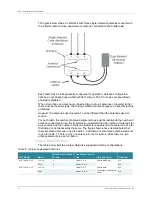
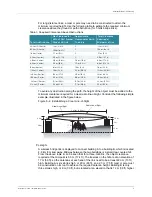
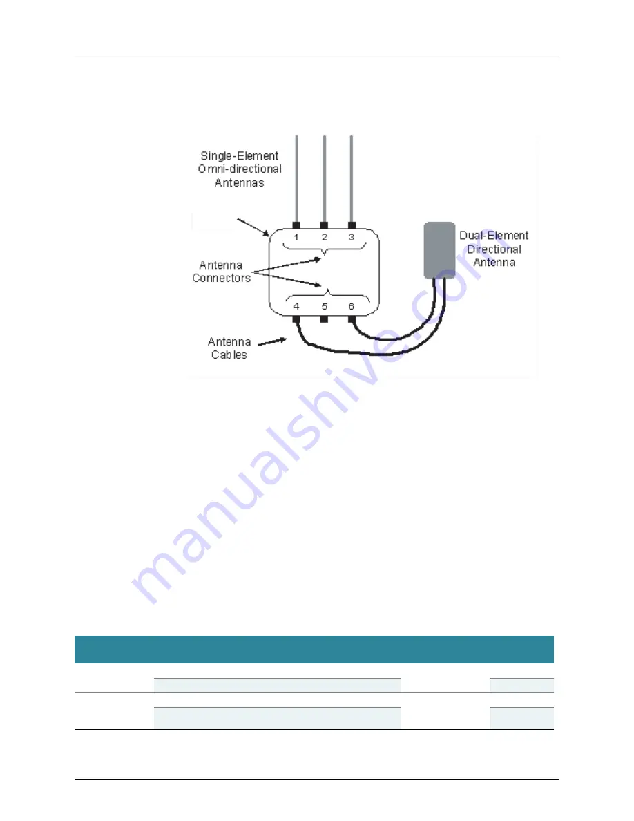
The figure below shows an WLA632 with three single-element antennas connected to
the 2.4GHz radio and one dual-element antenna connected to the 5GHz radio.
Each radio may be independently configured for operation. Antenna configuration
options do not depend upon whether 802.11a/b/g or 802.11n modes are specifically
enabled or disabled.
When more than one antenna is connected to a radio, all antennas connected to that
radio must be the same type. The mixing of different antenna types on a specific radio is
prohibited.
However, the antennas used on radio 1 can be different than the antennas used on
radio 2.
For each radio, the number of antenna elements in use will be identical to the number of
antenna connectors in use. It is important to understand that the number of antennas for
a given radio and the number of antenna elements (and antenna connectors) in use for
that radio are not necessarily the same. The figure shown above demonstrates that
there are three antennas in use for radio 1, and there are also three antenna elements
in use for radio 1. There is only one antenna in use for radio 2, while there are two
antenna elements in use for radio 2.
Supported Antennas
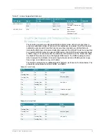
The table below lists the Juniper Networks supported antenna configurations.
WLA632
Table 11: Juniper Supported Antennas
ANT Model
Band
Number of Antennas
in Use
Connector Ports in
Use
Antenna Type
11n Mode
ANT-7360A-OUT
2.4GHz
3
Conn 1,2, & 3
Dual-band Omni
3x3
5GHz
3
Conn 4,5, & 6
3x3
ANT-74520-OUT
2.4GHz
1
Conn 1,2, & 3
Dual-band,
Tri element, Directional
Panel
3x3
5GHz
1
Conn 4,5, & 6
3x3


