12
13
ENGLISH
ENGLISH
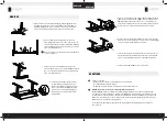
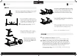
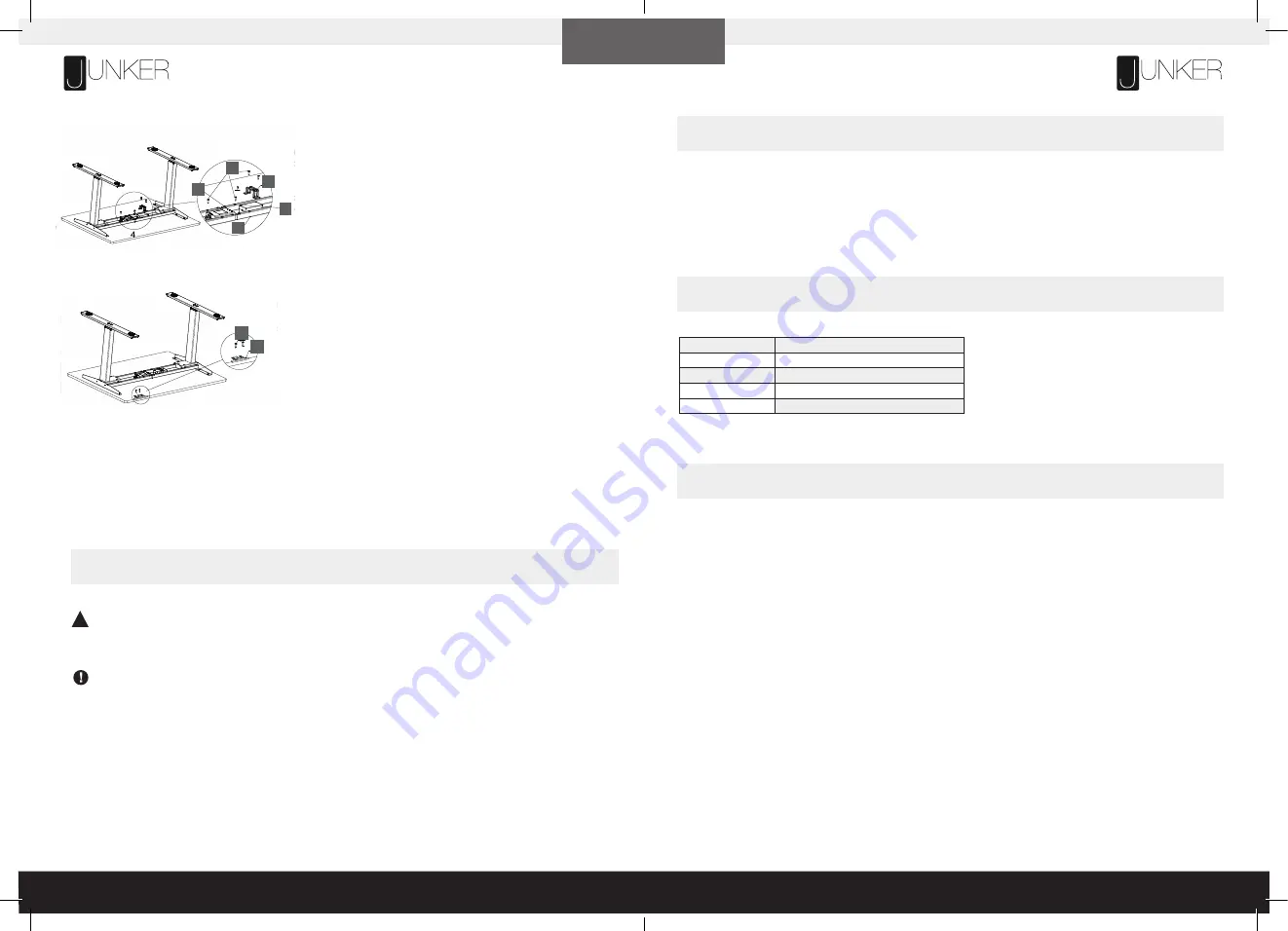
Attach the handset
(6)
to the underside of the table surface where you
want it. Fasten it with ST5 × 16 wood screws
(12)
. Plug the handset
cable into the control box.
Place the control box and adapter
(9)
into the middle of the frame
(2)
.
Fasten the screws
(10)
into the holes on both sides of the control box. Place
the adapter buckle
(8)
on the adapter, and fix the ST5 × 20 wood screws
into the holes on both sides of the adapter buckle. Plug the motor cable of the
column into the control box. Plug the cable of the adapter into the control box.
Plug the Power Cord
(15)
into a 230V outlet.
6.
8.
Putthecontrolboxandadapter(9)intothemiddleofthe
frame (2).Fix with tapping screw (10) into the holes on
bothsidesofthecontrolbox.Puttheadapterbuckle(8)
on the adapter, and fix the
ST5×20 wood screw
s
into
the holes on both sides of the adapter buckle. Plug the
motor wire of the column into the control box.Plug the
wireoftheadapterintothecontrolbox.
Double-check that the wood screws are not too long for your desktop
and won’t puncture the surface when screwed all the way in.
We recommend that you pre-drill any holes needed for fasteners
if your desktop is not pre-drilled. Never use countersunk screws.
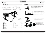
10
8
9
2
7
Put the handset (6) on the edge of the desktop where you
like. Fix with
S
T
5×16 wood screw
s (12) the handset on
the desktop. Plug the wire of the handset into the control
box.
6
12
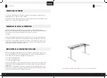
Turn the assembled desk right-side up. With at least two people, grab the DESK BASE (not the desktop) and turn the
desk right-side up. Adjust the pre-installed glides on the Feet (part 5) as needed.
Plug the Power Cord (part 15) into a 230V outlet.
5.
Turn the assembled desk right-side up. With at least two people, grab the
DESK BASE (not the desktop) and turn the desk right-side up. Adjust the
pre-installed sliders on the feet
(5)
as needed.
7.
Make sure no obstacles are in the desk’s path when adjusting its height.
Make sure the desktop is not touching any walls.
Make sure all cords have the appropriate length to accommodate the change in height.
IMPORTANT: You must RESET the desk prior to use.
RESET PROCEDURE: Press and hold the DOWN button on the handset (part 6) until the desk reaches the lowest
possible height. Release the DOWN button. Press and hold the DOWN button again until the LED display reads “RST”
or about 10 seconds on non-LED handset models. Release the DOWN button. Press and hold the DOWN button again
until the desk sinks a little bit more, slightly rises and stops. Release the DOWN button. Your desk is now ready to use.
The desk base can be adjusted by pressing and holding either the UP or DOWN button until the desired height
is reached.
USE
!
PROGRAMMING
Press the DOWN button on the Handset
(6)
until the desk reaches its lowest position. Release the DOWN button. Press
and hold the DOWN button again until the LED display reads „RST“. Release the DOWN button. Press and hold button 1
for about 5 seconds while the LED flashes „RST“ and the following, alternating displays appear:
10.1 = One-Touch
10.2 = Constant-Touch
Release button 1. Press button 1 again until the desired setting is reached. Once the chosen setting is displayed,
release the button and wait about 5 seconds for the display to return to „RST“.
Finish the reset process by pressing and holding the DOWN button until the desk lowers a little bit more, slightly rises
and stops. Release the button. The new program setting is saved and your desk is now ready to use.
If your desk is not functioning properly it may need to be reset. Follow the RESET procedure outlined in the USE section.
If the error message persists after the reset procedure, contact your seller.
If the height between the legs exceeds 38 mm, stop the reset procedure & contact your seller.
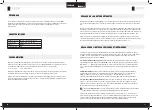
SPECIFICATIONS
TROUBLESHOOTING
Height Range
590 mm – 1240 mm (without desktop)
Base Width
1080 mm min. – 1600 mm max.
Speed
32 mm/s
Load Capacity
800N
Duty Cycle
10 % Max. 2 mins on, 18 mins off


