E
XTRAORDINARY MAINTENANCE MANUAL
-
CT
R
EV
.
01
20-05-2016
10 / 20
Jurop
SpA
Via Crosera n° 50
33082 Azzano Decimo, PN (Italia)
T
EL
.
+39
0434
636811
F
AX
.
+39
0434
636812
http://www.jurop.it
e-mail: info@jurop.it
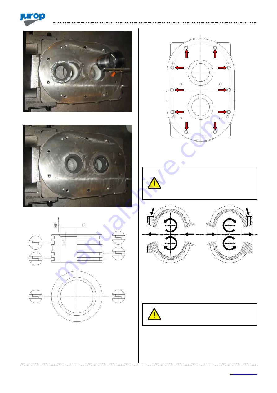
Fig. 5.5
Fig. 5.6
Fig. 5.7
Fig. 5.8
Assembling of the front bench
The pump’s rotation direction will determinate
which side of the housing the front bench
assembly has to be mounted. The temperature
control feeler seat must face upwards and the
injection-slots are indicating which one is the
exhaust port.
Fig. 5.9
• Once identified the housing’s side facing the front bench
assembly, insert the pins Ø10x35 (4 pcs) in the housing’s seats and
apply an even & thin coat of high-temperatures (250°C) sealing-glue.
Clean all the surfaces and check for eventual
damages / scratches before assembling.
Make sure of this prior coupling and/or
assembling.
• Careful center the bench in the guiding pins.
• Make sure that the draining slots are facing downwards.
• Tighten the screws M8x30 (10 pcs) fixing the flange to the
housing.
• Clean the sealing-glue residuals inside the housing.


