E
XTRAORDINARY MAINTENANCE MANUAL
-
CT
R
EV
.
01
20-05-2016
16 / 20
Jurop
SpA
Via Crosera n° 50
33082 Azzano Decimo, PN (Italia)
T
EL
.
+39
0434
636811
F
AX
.
+39
0434
636812
http://www.jurop.it
e-mail: info@jurop.it
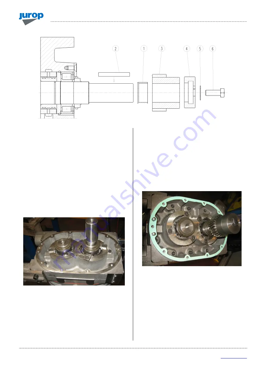
Assembling of the gear overdrive unit
Fig. 5.22
• The gear overdrive unit is installed as an alternative to the front
carter.
• Mount the spacer having thickness of 18mm instead of the
splashing oil disc unit in the lower shaft.
• Insert no. 4 pins Ø10x30 in the front bench and mount the related
gasket.
• Mount the overdrive driven gear components in the following
order:
-
Spacer (1).
-
Tab (2).
-
Overdrive drived gear (3).
-
Spacer (4).
-
Safety washer (5).
-
Screw M12 (6).
• Bend the safety washer to block the screw rotation.
Fig. 5.23
• Mount the overdrive housing careful centering the guiding pins.
• Tighten the screws M8 (10 pcs) with the relative grower washers
fixing the overdrive housing to the bench.
• Mount the rear bearing (22207 E/C3) of the overdrive driving shaft:
-
Oil the bearing seat.
-
Insert the bearing using the tool no. 7.
• Oil the internal ring of the bearing and mount the overdrive driving
shaft.
• Insert no. 4 Ø10x20 pins in the overdrive housing and mount the
relative gasket.
• Mount the front overdrive cover with bearing support.
• Tighten the screws M8 (10 pcs) with the relative grower washer
fixing the front overdrive cover.
• Mount the front bearing (21309 E/C3) of the overdrive driving
shaft:
-
Oil the bearing seat.
-
Insert the bearing using the tool no°7.
Fig. 5.24


