REV
.
11
30-05-2017
INSTALLATION
,
USE AND MAINTENANCE MANUAL
JULIA 3000-5000-7000-8000-8500-9000
-
HP
24 / 51
Jurop
SpA
Via Crosera n° 50
33082 Azzano Decimo, PN (Italy)
T
EL
.
+39
0434
636811
F
AX
.
+39
0434
636812
http://www.jurop.it
e-mail: info@jurop.it
α
α
1
α
α
1
4.1.
Checking upon receipt
• Remove packaging and eliminate material that could be
dangerous if sucked.
• When the goods are delivered, make sure that all parts listed on
the delivery note are in perfect condition and have suffered no damage
during shipping.
• Make sure the Julia group end the vacuum pump has its
identification plate affixed on the front cover. Pumps without such
identification are to be considered anonymous and potentially
dangerous: in such an event, they must not be used, otherwise the
manufacturer will be deemed free from any liability whatsoever.
• If the machine does not intend to be used for a long time it must
be stored in a closed dry place, the intake and exhaust ports need to
be protected with suitable caps in order to avoid the introduction of
foreign matter that could block or compromise subsequent functioning
and the overall state of conservation must be periodically renewed.
4.2.
Mounting
• The mounted Julia group must be accessible for maintenance and
firmly fixed on a frame or angled base with a 3° max inclination on x
and y axes. The structure must be fit to avoid flexions or vibrations.
• Make sure that there is enough free room around the pump for a
correct air cooling circulation and protect the pump from the exposure
to dirt and debris.
• Prepare the necessary space for an easy access to the lubrication
check-points (tank level and gear box, oilers, ecc).
• Mind the room necessary to levers operation.
4.3. Cardan shaft drive
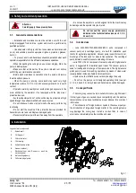
• Use telescopic cardan shafts.
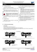
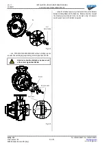
Fig. 4.2
• In order to achieve a uniform motion of the driven shaft, the
following requirements must be met (see Fig. 4.2):
- Equal working angle α and α1 of both couplings;
- The internal fork joints must be coplanar;
- Both driven and driving shafts must be coplanar.
• It is also recommended working with limited articulated joint angles
(max 15°) and disengaging the transmission for those operations
requiring great angles (steering or lifting).
Follow the rotation direction as indicated on the
front flange. Follow the instructions of the cardan
shaft’s manufacturer.
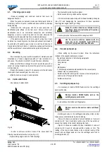
• Use the protection that comes with the Julia group shaft.
Use the cardan protection supplied with the
pump. The pump installation must fulfill the
current EC injury prevention specifications.
4.4.
Vacuum pump set up
• When setting up the vacuum system, follow the instructions
included in the use and maintenance manual.
Pay particular attention to the following paragraphs:
-
Connection to tank;
-
Pump start up;
-
Use;
-
Maintenance.
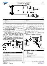
• The following accessories are available for the vacuum pump:
-
Exhaust silencer (vacuum pump);
-
Suitable safety filter and/or purifier on vacuum line (compulsory) to
avoid suction of foreign matter or liquids;
-
Suitable safety valves.
4.5.
Centrifugal pump set up
• It is necessary to install a DN200 flexible joint on the centrifugal
pump suction side.
Warning: install a DN200 flexible joint on the
centrifugal pump suction side.
• Avoid solids suction inside centrifugal pump.
Warning: avoid solids suction inside centrifugal
pump.
• Install a gate valve on the centrifugal pump exhaust side in order
to keep vacuum inside the tank while it is loading.
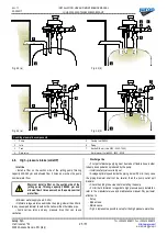
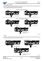
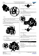
• Picture 4.3 shows an example of proper installation of Julia unit
complete with 1 lever to alternate running one of the two outlets: a)
vacuum the material in the tank b) discharge the tank..
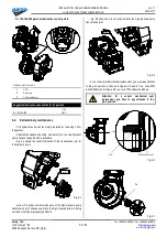
• Figure 4.4 shows an example of proper installation of Julia unit
complete with 2 levers to alternate-combine running (a & b). The
loading of the tank is made thanks to the combined running of the
vacuum and centrifugal pump (a). Use the centrifugal pump only to
discharge the tank (b).

