REV
.
11
30-05-2017
INSTALLATION
,
USE AND MAINTENANCE MANUAL
JULIA 3000-5000-7000-8000-8500-9000
-
HP
25 / 51
Jurop
SpA
Via Crosera n° 50
33082 Azzano Decimo, PN (Italy)
T
EL
.
+39
0434
636811
F
AX
.
+39
0434
636812
http://www.jurop.it
e-mail: info@jurop.it
1
2
3
6
4
4
5
4
7
5
4
4
6
1
2
4
5
7
3
3
3
4
4
4
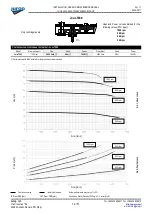
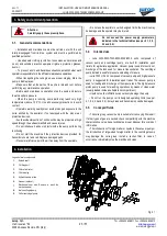
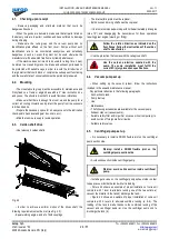
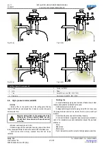
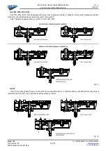
Fig. 4.3 (a)
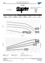
Fig. 4.3 (b)
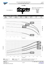
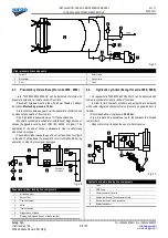
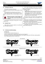
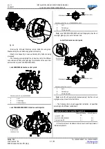
Fig. 4.4 (a)
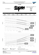
Fig. 4.4 (b)
Centrifugal pump line components
1
Pump
5
Flexible Joint DN200
2
Julia
6
Piping
3
Tank
7
Nozzle Ø34 mm (Julia 3000 - 5000 - 7000)
4
Gate valve
Slurry injector ) Julia 8000 - 8500 - 9000)
4.6.
High - pressure intake
(Julia HP)
Inlet line
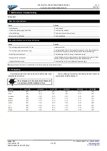
• Install a filter on the suction side of the jetting pump, filtering
capacity 200-360 µm and allowed flow 3 times as much as the pump
nominal water flow.
Warning: install a filter on the suction side of the
jetting pump, filtering capacity 200-360 µm and
allowed flow 3 times as much as the pump nominal
water flow.
• Minimum water supply head: 0.20 m.
• Optimal average water speed inside the piping: slower than 0.5m/s.
In any case pipe diameter should not be narrower than the intake pipe.
• Avoid narrow turns and any pressure drop that can cause
cavitation.
Discharge line
• First part of discharge piping must be made of flexible hose in order
to damp down pulsations produced by the pump.
• Install a safety valve correctly set.
• Average optimal speed inside the piping: below 5,5 m/s. In any case
the piping diameter shall not be smaller than the pump outlet port
diameter.
• Check the piping to be clean before starting the pump.
• For further information in regards to high pressure pump installation,
refer to the manufacturer use and maintenance manual. Pay particular
attention to:
-
Set up;
-
Mode of use;
-
Maintenance.
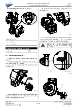
• Fig 4.4 represents a possible set up for the high pressure water line.


