REV
.
11
30-05-2017
INSTALLATION
,
USE AND MAINTENANCE MANUAL
JULIA 3000-5000-7000-8000-8500-9000
-
HP
26 / 51
Jurop
SpA
Via Crosera n° 50
33082 Azzano Decimo, PN (Italy)
T
EL
.
+39
0434
636811
F
AX
.
+39
0434
636812
http://www.jurop.it
e-mail: info@jurop.it
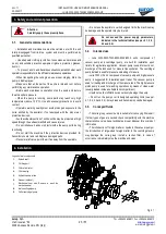
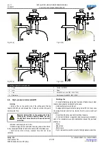
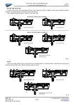
Fig.4.5
High - pressure line components
1
Julia HP
4
Safety valve
2
Manometer
5
Control valve
3
Filter
6
Tank
4.7.
Pneumatic cylinders (Except for Julia 3000 - 5000)
• Julia 7000-8000-8500-9000-HP can be delivered complete with
pneumatic cylinders for remote control of functions.
• Pneumatic cylinders must be fed with 20 µm filtered air without
lubrication.
Max feeding pressure 10 bar
.
• Avoid collisions between gears: set the pneumatic cylinder speed
by means of pneumatic air flow controls.
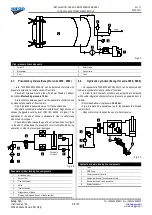
• Fig 4.5 represents a possible set up for the pneumatic line.
• Pneumatic cylinders are suitable for installation of magnetic end of
strokes (Suggested security level IP65 IEC 60529 or higher). The
application of the end of stroke is advisable in order to understand
when the exit is in gear.
• Pneumatic cylinder keeps the gear in correct position once it gets
to the end of stroke Keep the pneumatic circuit constantly fed during
operation, in order to prevent gear damages.
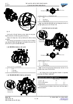
Fig. 4.6
Pneumatic cylinder feeding line components
1
Air feeding point
2
Suction filter
3
Flow controllers
4
Valve
5
Flow controllers
6
Magnetic end of stroke
7
Warning light (signals the end of stroke position)
4.8.
Hydraulic cylinders (Except for Julia 3000 - 5000)
• On request Julia 7000-8000-8500-9000-HP can be delivered with
hydraulic cylinders for remote control of functions.
• In order to limit hydraulic cylinder push, actuators are delivered
with double integrated shockproof valve (pressure on powered duct is
limited).
• Recommended service pressure:
30-40 bar.
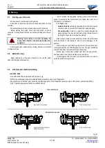
• Fig. 4.6 represents a possible set up for the hydraulic line (Closed
center circuit).
• Open center circuit required the use of a blocking valve.
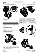
Fig. 4.7
Hydraulic actuators feeding line components
1
Tank
2
HDR Pump
3
Overpressure safety valve
4
Hydraulic distributor (closed center circuit)
5
Double shockproof valve (enclosed)
6
Hydraulic actuator
P
NEUMATIC
CYLINDER
2
5
4
1
3
6
7
1
2
3
4
5
6
1
3
2
4
5
6

