background image

DE

  |  JUST Normlicht GmbH  |  Ve Produktion  |  Tobelwasenweg 24  |  73235 Weilheim / Teck  |  Telefon: +49 (0) 7023 9504-0  |  Fax: +49 (0) 7023 9504-52 

US

  |  JUST Normlicht Inc.  |  2000 Cabot Blvd. West, Suite 120  |  Langhorne, PA 19047-2408  |  Telefon: +1 267 852 2200  |  Fax: +1 267 852 2207  

FR

  |  JUST Normlicht France SARL  |  3 Rue Louis Pasteur  |  67240 Bischwiller  |  Telefon: +33 (0)3880628-22  |  Fax: +33 (0)3880628-23

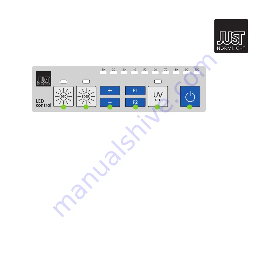
(A) Switch on illuminant D50 according to ISO 3664:2009

(B) Switch on illuminant D65 according to ISO 3668

(C) Continuously dimming of illuminants (see LEDs above)

(D) Switch off UV content

(E) On / Off button for standby mode

Commissioning

1.  Turn on the luminaire by pressing the black main power 

button.

2.  Choose illuminant (A or B) and confirm with (F). The 

diode above the switch of the active illuminant is shining 
green.

3.  If required, you can dimm the luminaire (C) or switch off 

UV content of illuminant D50 / D65 (E). A red diode is 
shining if UV content is switched off.

4.  Turn off the light when you finished the color assessment 

(F). After that you can switch off the luminaire completly 
by pressing the black main power button.

Notes


ƒ

If you switch on the luminaire again, the last set values 
will be stored


ƒ

You should shut down the luminaire by pressing the 
On / Off button (F) before you switch off the main power.


ƒ

You can change continuously illuminants (A, B and UV) 
without pressing (F).


ƒ

Press and hold "P1" or "P2" button to store the current 
dimm value – double blink of all LEDs. By pressing 
shortly one of the buttons, the preseted dimm value will 
be loaded – single blink of all LEDs.

A

B

C

D

E

F

LED-CONTROL


V.2

Operating Instructions

Summary of Contents for Just LED moduLight 1-800

Page 1: ...nleitung Assembly Instructions Instructions de Montage Just LED moduLight 1 800 Artikel Nr Item No REF 201620 201621 US Teileliste Part list Montageanleitung Assembly instructions Positionierung Positioning LED Steuerung LED control Techn Information Technical information Zubehör Ersatzteile Montageanweisung Aufhängung Seile Optimale Position Bohrplan Bedienungsanleitung Überspannung Fittings repl...

Page 2: ...lheim Teck Fon 49 0 70 23 95 04 0 Fax 49 0 70 23 95 04 52 FRA Just France SARL 3 Rue Louis Pasteur F 67240 Bischwiller Fon 33 0 3 88 06 28 22 Fax 33 0 3 88 06 28 23 USA Just USA Inc 2000 Cabot Blvd West Suite 120 Langhorne PA 19047 2408 Fon 1 267 852 2200 Fax 1 267 852 2207 ...

Page 3: ...rochage au plafond Stahlseilende durch die Stahlseilaufnahme führen Conduct the end of the steel cable to the holder Passer l extrémité du câble dans la tige de fixation Befestigung aller Stahlseile nach gleicher Vorgehensweise Mount all steel cable at the same way Procéder de la même facon pour le deuxiéme câble Höheneinstellung highness adjustment Réglage de la hauteur Über die Funktion der Höhe...

Page 4: ...Cheville Schraube Screw Vis Gewindeverschluss Threaded cap Support de câble Stahlseil Wire cable Câble en acier Stahlseilaufnahme Wire cable holder Tige de fixation du câble Stahlseilende hier durchführen Pass wire cable end here Faire sortir l extrémité du câble par là Fixierung des Stahlseiles hier lösen Loosen wire cable fixing here Ergot de relâchement du câble 1 2 4 3 4 ...

Page 5: ... moduLight optimal positioning for the LED moduLight Positionnement idéal du LED moduLight 3 Ausleuchtungsfläche plane of illumination zone de couverture Bohrplan Distance of bores Plan de percage LED moduLight 400 5 700 30 50 30 400 ...

Page 6: ...e Diode über dem Schalter der aktiven Lichtart leuchtet 3 Bei Bedarf dimmen Sie die Leuchte C oder schalten Sie den UV Anteil von D50 D65 Normlicht gezielt ab E Eine rote Diode leuchtet bei deaktiviertem UV Anteil 4 Nach Ihrem Abmusterungsvorgang schalten Sie die Leuchte aus F Danach können Sie die Leuchte über den schwarzen Hauptschalter komplett ausschalten Hinweise Beim erneuten Anschalten der ...

Page 7: ...d confirm with F The diode above the switch of the active illuminant is shining green 3 If required you can dimm the luminaire C or switch off UV content of illuminant D50 D65 E A red diode is shining if UV content is switched off 4 Turn off the light when you finished the color assessment F After that you can switch off the luminaire completly by pressing the black main power button Notes If you ...

Page 8: ...HNICAL INFORMATION How to protect the appliance from overvoltage Electrostatic Voltagepeaks Overloads and other killing pulses caused by the local electricity network can destroy the sensitive electronic ballasts in your appliance The reason for overvoltage can be a lightning strike up to 3km away or e g all other electrical devices elevators welding apparatus or machinery in your surrounding Dama...

Reviews: