


16
www.juwent.com.pl
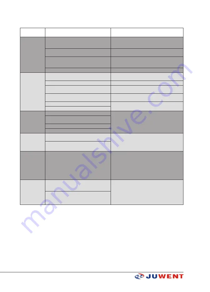
13. TROUBLESHOOTING
Trouble
description
Possible trouble cause
Troubleshooting
heat exchanger le-
akage
mechanical damage of heat exchanger (it may easy
appear when the unit is connected to the installation
without taking care
use a locking spanner to mount with the installation de-
finitely
exceedance of admissible heating medium para-
meters
connect the unit with the heating installation protected
against the excessive pressure and temperature growth
heat exchanger freeze
use an antifreeze thermostat, antifreeze heating fluids or
remove water from the unit within the period of standstill
and freeze risk
use of the unit in the aggressive environment
too load operation
of the unit
minimum distance from the wall or ceiling is not
maintained
use distances recommended in the instruction manual
improper revolution direction
execute a proper electric connection
improper parameters of the mains
use the unit only when the parameters of the mains and
the unit are compliant
air outlet is blocked by outlet grid louvres
avoid a significant closing of outlet grid louvres at high
speed ratios
fan vibrations, the blades rub against fixed elements check up the correctness of the fan and fastening reliabi-
lity of other elements of the unit
not centric fastening of the fan in its bearing plate
fan does not work
incorrect or unreliable electric connections
check up or correct:
1) compliance of electric connections according to the
diagrams specified in the instruction manual
2) reliability of connections on electric terminals
3) parameters of the mains
improper parameters of the mains (lack of three
phases in three-phase motors)
fan motor is damaged
fan operation control elements are damaged
Revolution con-
troller
ARW/RTRD does
not work
correctness of electric connections (whether the le-
ads are just clamped in the electric terminals)
check up or correct:
1) compliance of electric connections according to the
diagrams specified in the instruction manual
2) reliability of connections on electric terminals
3) parameters of the mains
only 1 controller can be connected to 1 unit
Servomotor does
not open the valve
correctness of thermostat operation (characteristic
“tick” when switching)
check up or correct:
1) compliance of electric connections according to the
diagrams specified in the instruction manual
2) reliability of connections on electric terminals
3) parameters of the mains
4) whether the servomotor reacts to an electric pulse. If
the servomotor damage is stated, the damaged element
should be claimed.
Room thermostat
does not apply the
signal
more than one unit is connected directly to the
thermostat (larger number means the thermostat
overload)
check up or correct:
1) compliance of electric connections according to the
diagrams specified in the instruction manual
2) reliability of connections on electric terminals
3) parameters of the mains
4) if there is no characteristic “tick”, the thermostat is me-
chanically damaged and should be claimed.
mounting place of the thermostat in the room
14. INFORMATION
As to all issues concerning the TROPIC heating units please contact JUWENT Production Plant or
Representatives


