
KS-UBT1
1
Only for KW-AVX838/KW-AVX738
Sólo para KW-AVX838/KW-AVX738
Only for KW-AVX838/KW-AVX830
Sólo para KW-AVX838/KW-AVX830
KW-AVX838/KW-AVX830/KW-ADV793/KW-AVX738/KW-AVX730
Installation/Connection Manual
Manual de instalación/conexión
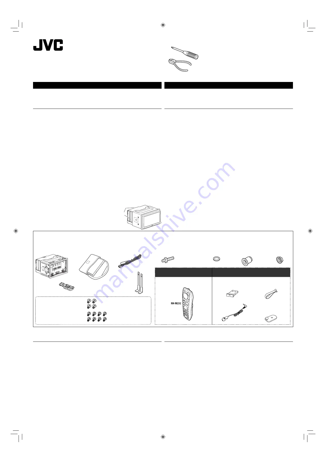
Parts list for installation and connection
The following parts are provided for this unit.
If anything is missing, contact your dealer immediately.
ENGLISH
This unit is designed to operate on
12 V DC, NEGATIVE ground electrical systems
. If your vehicle does
not have this system, a voltage inverter is required, which can be purchased at JVC car audio dealers.
WARNINGS
• DO NOT install any unit or wire any cable in a location where;
– it may obstruct the steering wheel and gearshift lever operations, as this may result in a traffic accident.
– it may obstruct the operation of safety devices such as air bags, as this may result in a fatal accident.
– it may obstruct visibility.
• DO NOT operate any unit while manipulating the steering wheel, as this may result in a traffic accident.
• The driver must not watch the monitor while driving. It may lead to carelessness and cause an accident.
• If you need to operate the unit while driving, be sure to look around carefully or you may be involved in
a traffic accident.
• If the parking brake is not engaged, “Parking Brake” appears on the monitor, and no playback picture
will be shown.
– This warning appears only when the parking brake lead is connected to the parking brake system built
in the car.
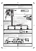
To prevent short circuits, we recommend that you disconnect the battery’s negative terminal and make all
electrical connections before installing the unit.
•
Be sure to ground this unit to the car’s chassis again after installation.
• Be sure any cable is not caught on the car’s chassis or under seats.
Notes on electrical connections:
• Replace the fuse with one of the specified rating. If the fuse blows frequently, consult your JVC car audio
dealer.
• It is recommended to connect speakers with maximum power of more than 50 W (both at the rear and
at the front, with an impedance of
4 Ω
to
8 Ω
).
If the maximum power is less than 50 W, change <Amplifier Gain> setting to prevent the speakers from
being damaged (see page 35 of the INSTRUCTIONS).
• To prevent short circuits, cover the terminals of the UNUSED leads with insulating tape.
• The heat sink becomes very hot after use. Be careful
not to touch it when removing this unit.
• At the time of installation, be sure to fix all wires
(wires both from this unit and from the car itself) in
a way that any wires cannot come into contact with
heat sinks on the rear and side of the unit.
Heat sink
Sumidero térmico
LVT2087-001B
[J/JW]
0110NYMMDWJEIN
EN, SP
© 2010 Victor Company of Japan, Limited
Round head screws (M5 x 8 mm/M5 x 3/8”)
Tornillos de cabeza esférica
(M5 x 8 mm/M5 x 3/8 pulgada)
Flat head screws (M5 x 8 mm/M5 x 3/8”)
Tornillos de cabeza plana
(M5 x 8 mm/M5 x 3/8 pulgada)
Main unit/Sleeve/Trim plate
Unidad principal/Cubierta/Placa
de guarnición
Power cord
Cordón de alimentación
Remote controller
Control remoto
Crimp connector
Conector de sujeción
Use these screws when installing
the unit without the supplied sleeve.
(See below.)
Utilice estos tornillos cuando
instale la unidad sin la cubierta
suministrada. (véase abajo)
Monitor panel and soft case
Panel del monitor y estuche blando
Microphone holder
Soporte del micrófono
Microphone clip
Presilla para micrófono
Bluetooth adapter (See page 4.)
Adaptador Bluetooth (Consulte la
página 4.)
Microphone
Micrófono
Handles
Manijas
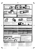
INSTALLATION (IN-DASH MOUNTING)
The following illustration shows a typical installation. However, you should make adjustments
corresponding to your specific car. If you have any questions or require information regarding installation
kits, consult your JVC car audio dealer or a company supplying kits.
• If you are not sure how to install this unit correctly, have it installed by a qualified technician.
Before installing the unit
• Remove the audio system originally installed in the car, together with its mounting brackets. Be sure to
keep all the screws and parts removed from your car for future use.
• When mounting the unit, be sure to use the screws provided, as instructed. If other screws are used,
parts could become loose or damaged.
• When tightening screws or bolts, be careful not to pinch any connection cord.
• Make sure not to block the fan on the rear to maintain proper ventilation when installing the unit.
• You cannot install the unit on the car which has any obstacles in the space shown in “Required space for
installation and the monitor panel ejection” on the following page.
When installing the unit without using the sleeve
• Use flat head screws or round head screws, depending on installation location. When you use flat head
screws to install the unit, use the screws removed in step 1 on the following page. When you use screws
other than those supplied, use 8 mm (3/8”)-long screws. If longer screws are used, they could damage
the unit.
• Tighten the screws firmly to prevent the unit from falling off.
Lista de piezas para instalación y conexión
Con esta unidad se suministran las siguientes piezas.
Si hay algún elemento faltante, póngase inmediatamente en contacto con su concesionario.
INSTALACIÓN (MONTAJE EN EL TABLERO DE INSTRUMENTOS)
La siguiente ilustración muestra una instalación típica. Sin embargo usted deberá efectuar los
ajustes correspondientes a su automóvil. Si tiene alguna pregunta o necesita información acerca de
las herramientas para instalación, consulte con su concesionario de JVC de equipos de audio para
automóviles o a una compañía que suministra tales herramientas.
• Si no está seguro de poder instalar la unidad correctamente, déjela en manos de un técnico cualificado.
Antes de instalar la unidad
•
Desmonte el sistema de audio instalado originalmente en el coche, junto con los ménsulas de montaje.
Asegúrese de guardar todos los tornillos y piezas quitados de su vehículo para poderlos usar en el futuro.
•
Al instalar la unidad, asegúrese de usar los tornillos suministrados, de acuerdo con las instrucciones.
El uso de otros tornillos podrá provocar flojedad de o daños a las piezas.
•
Al apretar los tornillos o los pernos, asegúrese de que ningún cable de conexión quede pillado.
•
Al efectuar la instalación, asegúrese de no bloquear el ventilador del panel trasero a fin de mantener
una ventilación correcta.
•
No podrá instalar la unidad en un coche en que haya algún obstáculo en el espacio indicado en
“Espacio requerido para la instalación y la expulsión del panel del monitor” en la página siguiente.
Instalación de la unidad sin utilizar la cubierta
•
Utilice tornillos de cabeza plana o esférica, dependiendo del lugar de instalación. Si decide utilizar
tornillos de cabeza plana para instalar la unidad, utilice los tornillos extraídos en el paso 1 de la
siguiente página. Si decide utilizar tornillos distintos de los suministrados, escoja tornillos de 8 mm
(3/8”) de largo. El uso de tornillos más largos producir daños a la unidad.
•
Apriete los tornillos firmemente para evitar que la unidad se caiga.
ESPAÑOL
Esta unidad está diseñada para funcionar con
12 V de CC, con sistemas eléctricos de masa
NEGATIVA
.
Si su vehículo no posee este sistema, será necesario un inversor de tensión, que puede ser
adquirido en los concesionarios de JVC de equipos de audio para automóviles.
ADVERTENCIAS
• NO instale ningún receptor o tienda ningún cable en una ubicación donde;
– donde pueda obstruir la maniobra del volante de dirección y del cambio de engranajes, con el
consiguiente riesgo de accidentes de tráfico.
– donde pueda obstruir el funcionamiento de dispositivos de seguridad tales como bolsas de aire,
pues podría resultar en un accidente fatal.
– donde pueda obstruir la visibilidad.
• NO OPERE la unidad mientras está maniobrando el volante de dirección, pues podría producirse un
accidente de tráfico.
• El conductor no debe mirar el monitor mientras conduce. Podría producirse un descuido, y causar un accidente.
• Si necesita operar la unidad mientras conduce, asegúrese de mirar atentamente a su alrededor pues
de lo contrario, se podría producir un accidente de tráfico.
• Si el freno de mano no está en uso, aparecerá “Parking Brake (Freno de Mano)” en la pantalla y no se
mostrará ninguna secuencia de imagen.
– Esta advertencia aparece únicamente cuando el cable del freno de estacionamiento se encuentra
conectado al sistema del freno de estacionamiento incorporado al automóvil.
Para evitar cortocircuitos, recomendamos que desconecte el terminal negativo de la batería y que
efectúe todas las conexiones eléctricas antes de instalar la unidad.
• Asegúrese de volver a conectar a masa esta unidad al chasis del automóvil después de la
instalación.
• Asegúrese de que ningún cable quede atrapado en el chasis del automóvil o debajo de los asientos.
Notas sobre las conexiones eléctricas:
• Reemplace el fusible por otro del régimen especificado. Si el fusible se funde frecuentemente,
consulte con su concesionario de JVC de equipos de audio para automóviles.
• Se recomienda conectar los altavoces con una potencia máxima de más de 50 W (tanto atrás como
adelante, con una impedancia de
4 Ω
a
8 Ω
).
Si la potencia máxima es de menos de 50 W, cambie <Amplifier Gain> para evitar daños en los
altavoces (consulte la página 35 del MANUAL DE INSTRUCCIONES).
• Para evitar cortocircuitos, cubra los cables NO UTILIZADOS con cinta aislante.
• El sumidero térmico estará muy caliente después del uso. Asegúrese de no tocarlo al desmontar esta unidad.
• Al realizar la instalación, asegúrese de fijar todos los cables (tanto los que proceden de esta unidad
como los del vehículo en sí) de manera tal que ninguno quede en contacto con los disipadores
térmicos de las partes traseras y laterales de la unidad.
Mounting bolt—M4
×
20 mm/M4 x 13/16”
Perno de montaje—
M4 x 20 mm/M4 x 13/16 pulgada
Rubber cushion
Cojín de goma
Washer (ø5)
Arandela (ø5)
Lock nut (M5)
Tuerca de
seguridad (M5)
Insta_KWAVX838[JWJ].indb 1
Insta_KWAVX838[JWJ].indb 1
10.5.7 10:29:38 AM
10.5.7 10:29:38 AM


