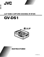
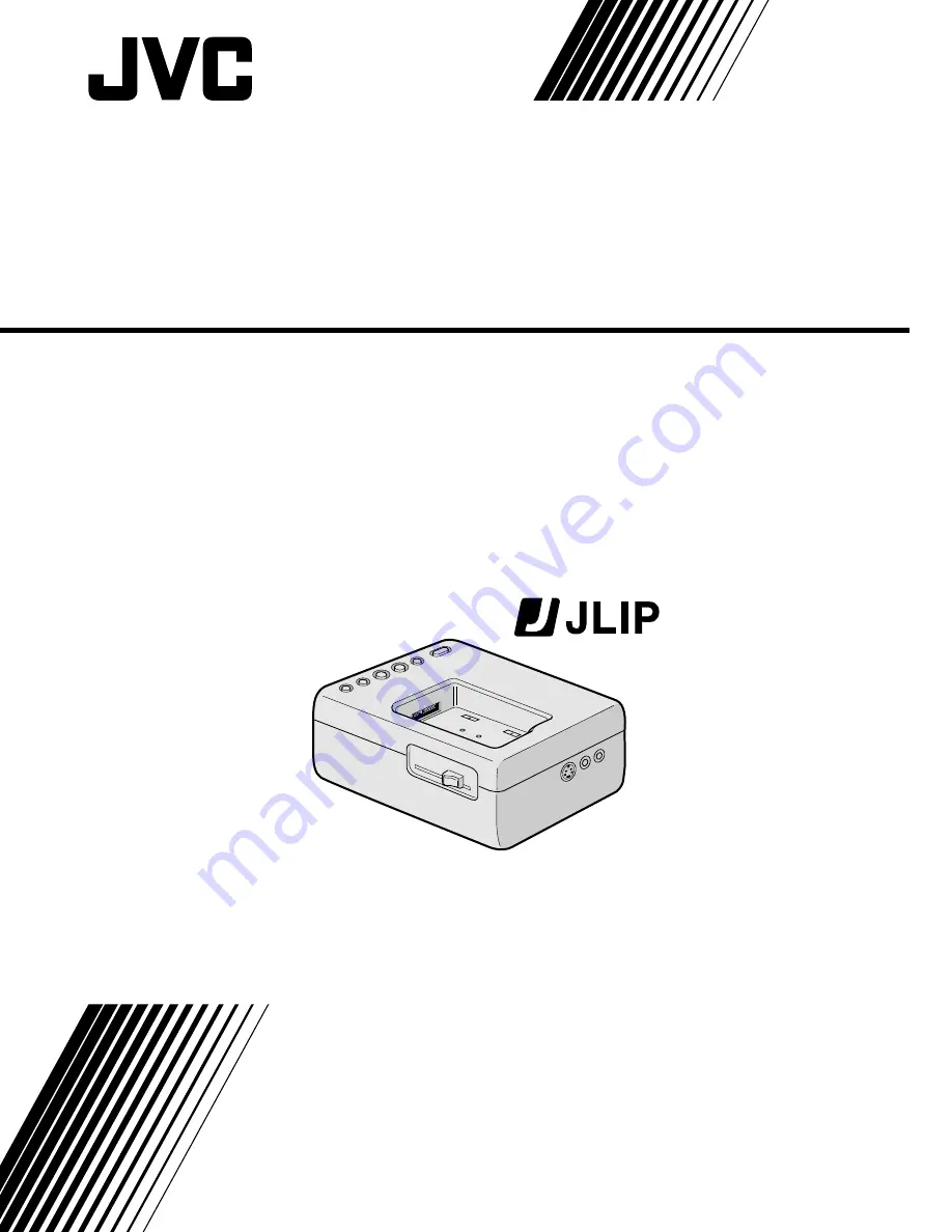
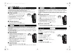
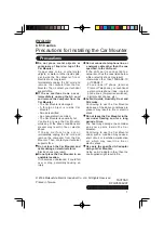
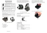
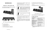
JVC 0397MKV*UN*VP, Instructions Manual
The JVC 0397MKV*UN*VP is an innovative product designed to enhance your digital experience. Featuring cutting-edge technology and user-friendly features, this device offers exceptional performance. For detailed instructions, download the free manual from 88.208.23.73:8080, ensuring a seamless setup and operation. Get the most out of your purchase hassle-free!
Share
Download
Reviews:
No comments
Related manuals for 0397MKV*UN*VP
CM615
Brand: UGREEN Pages: 8
Z Series
Brand: VDO Pages: 4
CF-WEB Series
Brand: Panasonic Pages: 2
CF-WEB184 Series
Brand: Panasonic Pages: 2
CF-WEB Series
Brand: Panasonic Pages: 20
DH60
Brand: Datalogic Pages: 2
Jet
Brand: Datalogic Pages: 2
Thunderbolt Station 2
Brand: CalDigit Pages: 14
iD100
Brand: Cambridge Audio Pages: 6

B-Series
Brand: WatchDog Pages: 4
Skorpio
Brand: Datalogic Pages: 2
Memor
Brand: Datalogic Pages: 2
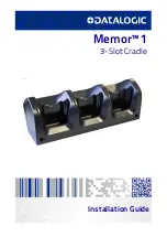
Memor 1
Brand: Datalogic Pages: 56
MWiD25-DS
Brand: Fantec Pages: 2
Platinum Edition
Brand: Gateway Pages: 16
The Cube
Brand: Hama Pages: 5
53161
Brand: Hama Pages: 16
53161
Brand: Hama Pages: 38


