Chapter 5---Electronics
5-46
Model 250 Service Manual
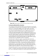
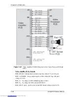
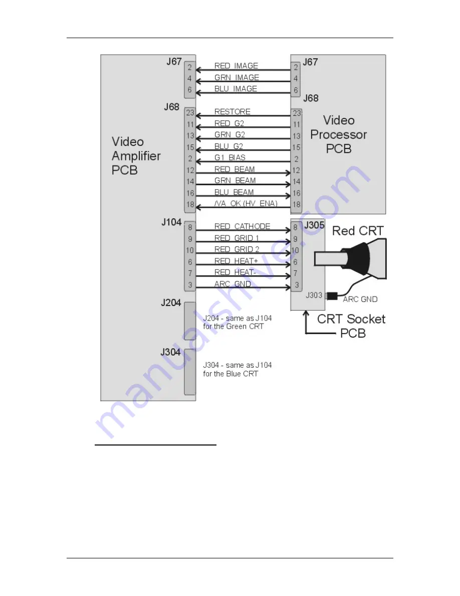
Figure 5-27
Video Amplifier PCB I/O Diagram for the Video Processor PCB and
CRTs.
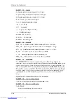
Video Amplifier PCB - Outputs
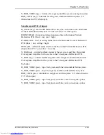
RGB_BEAM - Cathode beam current sense lines (about 1 V per 100 µA).
RGB_CATHODE - image output signal to CRTs (about 40 Vpp with peak
voltage of 70 V).
RGB_G
1
- G
1
voltage to CRTs (Blanking pulse to CRT).
RGB_G
2
- G
2
voltage for CRTs (about 600-800 V).
RGB_HEAT (pos.) - positive side of the CRT heater voltage (about 6.2 V).
Summary of Contents for 250
Page 16: ...Chapter 2 System Description Model 250 Service Manual 2 9 ...
Page 43: ...Chapter 4 Optical 4 10 Model 250 Service Manual Figure 4 6 Optical Path ...
Page 55: ...Chapter 5 Optical 3 4 22 Model 100 Service Manual ...
Page 91: ...Chapter 5 Electronics 5 36 Model 250 Service Manual Figure 5 22 Scan Reversal PCB I O Diagram ...
Page 131: ...Chapter 5 Electronics 5 76 Model 250 Service Manual Figure 5 44 Backplane Diagram right side ...
Page 132: ...Chapter 5 Electronics Model 250 Service Manual 5 77 ...
Page 138: ...Chapter 6 Miscellaneous Items 6 6 Model 250 Service Manual ...
Page 167: ...Chapter 7 Troubleshooting Model 250 Service Manual 7 29 ...
Page 181: ...Chapter 8 Software and Protocol 8 14 Model 250 Service Manual ...
Page 185: ...Chapter 9 Parts List 9 4 Model 250 Service Manual ...

