Chapter 2---System Description
Model 250 Service Manual
2-7
provides an interconnection interface for all the electronic components in
the projector.
CRT/Yoke Assemblies
The CRT/Yoke Assemblies bridge between the Optical and the Electronic
sections. The CRTs could be included in the Optical section because they
produces the image light transmitted to the ILA
®
s, but they are included in the
Electronic section because they are the end user for the image signals from the
VICs, Video Processor PCB, and Video Amplifier PCB. The CRTs also use the
Anode, Focus, G
1
, and G
2
voltages from the High Voltage Power Supply. The
Yoke Assemblies contains the deflection and convergence coils. The deflection
coils are the end-user for the horizontal and vertical deflection waveforms from
the Horizontal Vertical Deflection PCB. The convergence coils use the
convergence data from the Convergence Deflection PCB.
2.5
Miscellaneous Items
The Miscellaneous Items section consists of components that indirectly support
the main function of the projector.
Projector Covers
All Series 200 projectors including the Model 250 have a front and rear cover.
Both covers can be tilted up and/or removed to service the projector. The covers
should not be opened while the projector is operating without proper safety
protection (review the Safety Chapter).
IR Detectors
The Model 250 can be controlled by a handheld IR Remote Control. The IR
(Infrared) Detectors receive infrared pulses from these remote controls and use
them to control various functions of the projector. One IR Detector is mounted on
the front of the projector, the other is mounted on the System Controller PCB at
the rear of the projector. IR Detectors can receive commands from the remote
control from a range of about 45-ft. line of sight.
Cooling Fans
The Model 250 has eleven cooling fans of various sizes plus a large blower for
the Arc Lamp. The cooling fans maintain thermal stability for the projector. The
Arc Lamp especially depends on the cooling fans. If the fans are not operating
while the Arc Lamp is on, the Lamp will implode from overheating. Many of the
Printed Circuit Boards generate a lot of heat and require airflow from the cooling
fans. The fans provide cooling to the PCBs and CRTs to maintain for stable
operation.
Air Filters
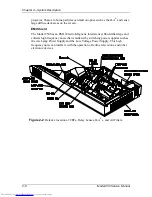
The Model 250 has three air filters (see Figure 2-2). The Air Filters filter the
incoming air to minimize the amount of dust and air-borne particles inside the
Summary of Contents for 250
Page 16: ...Chapter 2 System Description Model 250 Service Manual 2 9 ...
Page 43: ...Chapter 4 Optical 4 10 Model 250 Service Manual Figure 4 6 Optical Path ...
Page 55: ...Chapter 5 Optical 3 4 22 Model 100 Service Manual ...
Page 91: ...Chapter 5 Electronics 5 36 Model 250 Service Manual Figure 5 22 Scan Reversal PCB I O Diagram ...
Page 131: ...Chapter 5 Electronics 5 76 Model 250 Service Manual Figure 5 44 Backplane Diagram right side ...
Page 132: ...Chapter 5 Electronics Model 250 Service Manual 5 77 ...
Page 138: ...Chapter 6 Miscellaneous Items 6 6 Model 250 Service Manual ...
Page 167: ...Chapter 7 Troubleshooting Model 250 Service Manual 7 29 ...
Page 181: ...Chapter 8 Software and Protocol 8 14 Model 250 Service Manual ...
Page 185: ...Chapter 9 Parts List 9 4 Model 250 Service Manual ...


