Chapter 7---Troubleshooting
7-22
Model 250 Service Manual
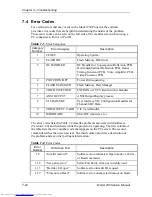
7.4 Error
Codes
For certain errors that may occur in the Model 250 Projector the software
provides error codes that are helpful in determining the nature of the problem.
These error codes can be seen on the left side of the monitor screen when using a
PC connected to Port A or Port B.
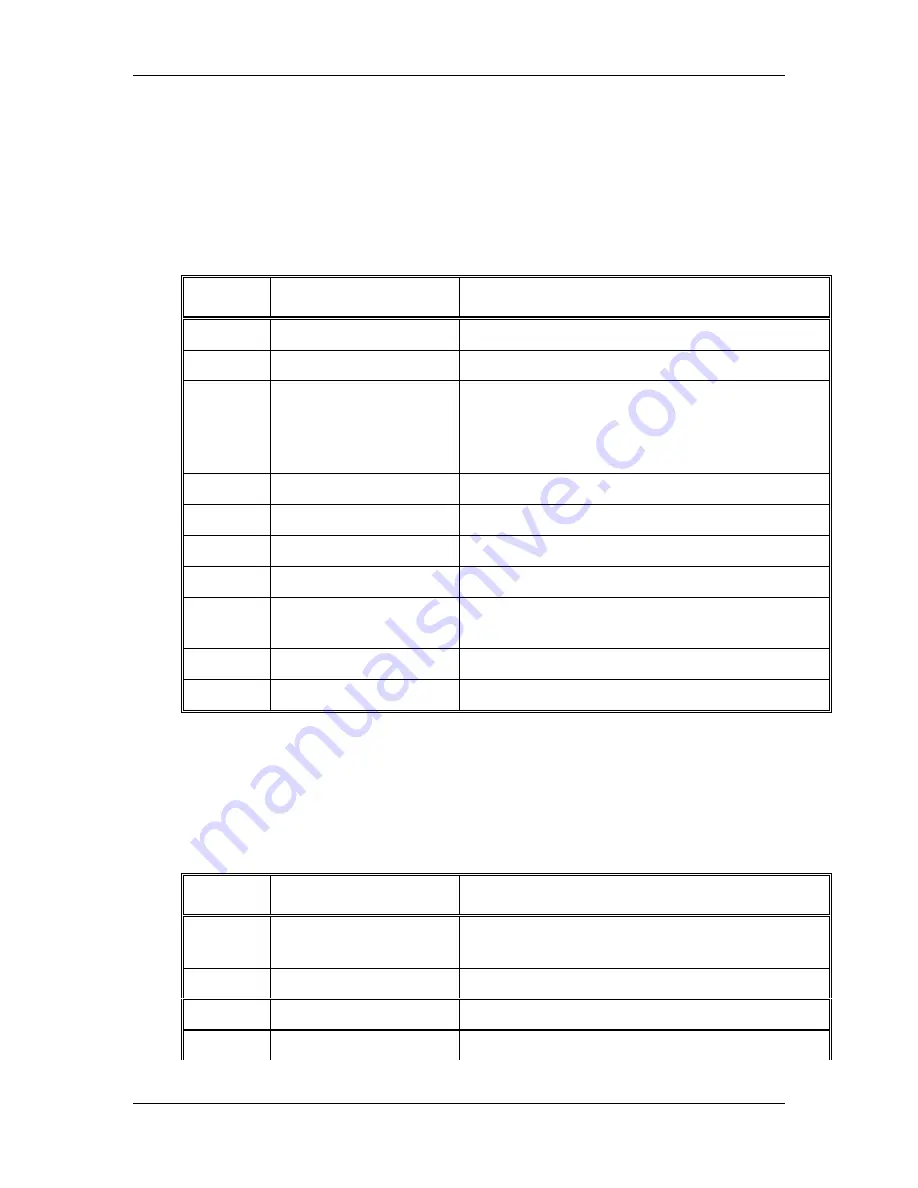
Table 7-1
Error Categories:
Category
Number
Error Category
Description
1
CEXEC
Operating System.
2
FLASH HW
Flash Memory HW driver.
3
IIC HANDLER
IIC Handler for Convergence/Deflection PCB,
Horizontal/Vertical Deflection PCB, Raster
Timing Generator PCB, Video Amplifier PCB,
Video Processor PCB.
4
POWER ON/OFF
Power On Sequencing.
5
FLASH MANAGER
Flash Memory Data Manager.
6
VIDEO SWITCHER
EXTRON or JVC Video Switcher Handler.
7
ANSI OUTPUT
ANSI Output Display process.
8
UI CHAN/SRC
User Interface VIC Configuration Handler for
Channel/SRC Data.
9
VIDEO INPUT CARD
VIC Card Handler.
10
HARDWARE
Misc HW (shutters, etc.).
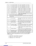
The error codes listed in Table 7-2 describe problems associated with software
(Version 2.6.0) and hardware while the projector is operating. The first column of
the table lists the error number code that appears on the PC screen. The second
column describes the on-screen text. The third column provides a description of
the problem and any other pertinent information.
Table 7-2
Error Codes.
Error
Number
On-Screen Text
Description
1.5
“Invalid read/wrt”
Software error-mismatch. Open mode vs. Write
or Read command.
1.12
“Ser parity error”
Serial Port Parity error-not currently used.
1.13
“Bad dev I/O oper”
Software error-invalid I/O request.
1.27
“Timeout on Read”
Software error-unexpected timeout on Read.
Summary of Contents for 250
Page 16: ...Chapter 2 System Description Model 250 Service Manual 2 9 ...
Page 43: ...Chapter 4 Optical 4 10 Model 250 Service Manual Figure 4 6 Optical Path ...
Page 55: ...Chapter 5 Optical 3 4 22 Model 100 Service Manual ...
Page 91: ...Chapter 5 Electronics 5 36 Model 250 Service Manual Figure 5 22 Scan Reversal PCB I O Diagram ...
Page 131: ...Chapter 5 Electronics 5 76 Model 250 Service Manual Figure 5 44 Backplane Diagram right side ...
Page 132: ...Chapter 5 Electronics Model 250 Service Manual 5 77 ...
Page 138: ...Chapter 6 Miscellaneous Items 6 6 Model 250 Service Manual ...
Page 167: ...Chapter 7 Troubleshooting Model 250 Service Manual 7 29 ...
Page 181: ...Chapter 8 Software and Protocol 8 14 Model 250 Service Manual ...
Page 185: ...Chapter 9 Parts List 9 4 Model 250 Service Manual ...


