Chapter 7---Troubleshooting
Model 250 Service Manual
7-23
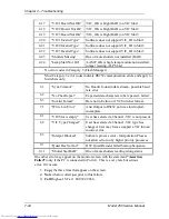
1.34
“No mem available”
Software error-no heap available for memory
allocation.
2.1
“Invalid Sector”
Software error-invalid Flash sector number.
2.2
“Write Timeout”
Flash Memory Write Failure.
2.3
“Erase Timeout”
Flash Memory Erase Sector Failure.
2.4
“Verify Error”
Flash Memory Write Verify Failure.
NOTE:
Category 3 error codes may occur when power is interrupted by opening the
cover interlock switches or during power brown-outs.
3.1
“Pin Timeout”
IIC Slave HW protocol error-possible on each
byte transfer.
3.2
“BB Timeout”
IIC Slave HW protocol error-1st error possible
on Read or Write.
3.3
“No Slave Ack”
IIC Slave HW protocol error-missing
acknowledgement on byte transfer. NOTE: This
error occurs if the slave is missing. During
Power On, this error is reported in the POWER
category.
4.1
“CD PCA Missing”
“No Slave Ack” on first poll of Convergence/
Deflection PCB.
4.2
“CD PCA Not OK”
/CD_OK is high (BAD).
4.3
“”HVD PCA Missing”
“No Slave Ack” status on first poll of
Horizontal/Vertical Deflection PCB.
4.4
“HVD PCA Not OK”
HVD_OK is High (BAD)-[/HVD_OK requires
RTG Timing.
4.5
“VA PCA Missing”
“No Slave Ack” status on first poll of Video
Processor.
4.6
“VA PCA Not OK”
/VA_OK is High (BAD).
4.7
“VP PCA Missing”
“No Slave Ack” status on first poll of VP.
4.8
“VP PCA Not OK”
VP_OK is High (BAD)
4.9
“RTG PCA Missing”
“No Slave Ack” status on first poll of RTG
4.10
“RTG PCA Not OK”
RTG_OK is High (BAD)
4.14
“Lamp Startup”
Lamp Failed to light (/LAMP_LIT_B not Low
for 3 seconds out of 20 seconds.)
4.15
“Low Voltage PS”
Low Voltage PS failed (/LV_OK_B is High).
4.16
“High Voltage PS”
High Voltage PS failed (/HV_OK_B is High).
Summary of Contents for 250
Page 16: ...Chapter 2 System Description Model 250 Service Manual 2 9 ...
Page 43: ...Chapter 4 Optical 4 10 Model 250 Service Manual Figure 4 6 Optical Path ...
Page 55: ...Chapter 5 Optical 3 4 22 Model 100 Service Manual ...
Page 91: ...Chapter 5 Electronics 5 36 Model 250 Service Manual Figure 5 22 Scan Reversal PCB I O Diagram ...
Page 131: ...Chapter 5 Electronics 5 76 Model 250 Service Manual Figure 5 44 Backplane Diagram right side ...
Page 132: ...Chapter 5 Electronics Model 250 Service Manual 5 77 ...
Page 138: ...Chapter 6 Miscellaneous Items 6 6 Model 250 Service Manual ...
Page 167: ...Chapter 7 Troubleshooting Model 250 Service Manual 7 29 ...
Page 181: ...Chapter 8 Software and Protocol 8 14 Model 250 Service Manual ...
Page 185: ...Chapter 9 Parts List 9 4 Model 250 Service Manual ...


