Chapter 7---Troubleshooting
7-24
Model 250 Service Manual
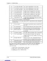
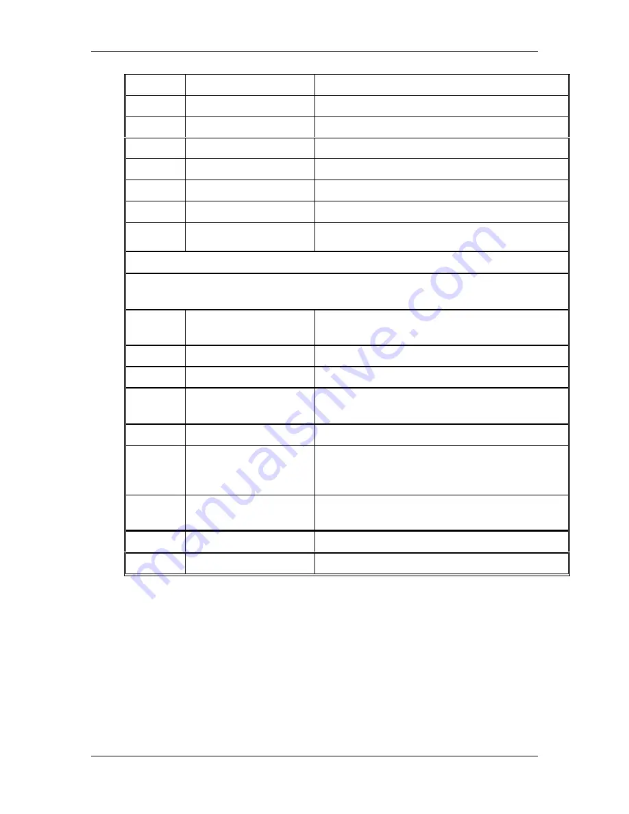
4.17
“VIC1 Board Not OK”
/VIC_OK is High (BAD) on VIC Slot 1.
4.18
“VIC 2 Board Not Ok”
/VIC_OK is High (BAD) on VIC Slot 2
4.19
“VIC3 Board Not OK”
/VIC_OK is High (BAD) on VIC Slot 3
4.20
“VIC1 Invalid Type”
Software does not support VIC_ID in Slot 1
4.21
“VIC2 Invalid Type”
Software does not support VIC_ID in Slot 2
4.22
“VIC3 Invalid Type”
Software does not support VIC_ID in Slot 3
4.23
“Shutters Missing”
One or more shutters not installed (BAD)
4.24
"Lamp Start Not On"
/LAMP_OK is high, lamp module not installed,
jumper missing, ALPS bad.
No error codes in Category 5 (Flash Manager)
Most Category 6 error codes indicate RS232 communication errors and apply to
Switchers only.
6.1
“Sync Timeout”
No Header found in data stream - possible baud
rate error.
6.2
“No Char Repeat”
Expected data characters to be repeated - failed.
6.3
“Invalid Format”
Data not in Extron or JVC Switcher format.
7.1
“Write Len Error”
Ansi Output to RS232 port was interrupted -
incomplete.
8.1
“VIC Slot is empty”
User has selected a Channel - VIC is not present.
8.2
“VIC Type Changed”
User has selected a Channel - VIC type has
changed. User may have swapped a VIC into an
incorrect slot.
8.3
“Interpol Blocked”
Software process error - Interpolation Process
not allowed to run by higher priority processes.
9.1
“Quad Dec Not Init”
HW: Quad Decoder failed Startup Sequence.
10.1
“Shutter Stat BAD”
One or more shutters reading wrong status.
One other error may appear on the monitor screen with the statement “Assertion
Failed” (only if the PC is connected to Port A). This is a very rare but serious
error. If it occurs:
1.
Copy the three lines that appear on the screen.
2.
Note what occurred just prior to this failure.
3.
Call Hughes-JVC at 1 800 392-9666.
Summary of Contents for 250
Page 16: ...Chapter 2 System Description Model 250 Service Manual 2 9 ...
Page 43: ...Chapter 4 Optical 4 10 Model 250 Service Manual Figure 4 6 Optical Path ...
Page 55: ...Chapter 5 Optical 3 4 22 Model 100 Service Manual ...
Page 91: ...Chapter 5 Electronics 5 36 Model 250 Service Manual Figure 5 22 Scan Reversal PCB I O Diagram ...
Page 131: ...Chapter 5 Electronics 5 76 Model 250 Service Manual Figure 5 44 Backplane Diagram right side ...
Page 132: ...Chapter 5 Electronics Model 250 Service Manual 5 77 ...
Page 138: ...Chapter 6 Miscellaneous Items 6 6 Model 250 Service Manual ...
Page 167: ...Chapter 7 Troubleshooting Model 250 Service Manual 7 29 ...
Page 181: ...Chapter 8 Software and Protocol 8 14 Model 250 Service Manual ...
Page 185: ...Chapter 9 Parts List 9 4 Model 250 Service Manual ...

