Chapter 8---Software and Protocol
8-4
Model 250 Service Manual
Boot Manager Ver y.y.0 (Service Mode Startup)
Copyright (c) 1994-1996 Hughes-JVC
Technology
Command: _
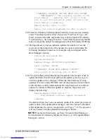
12A. To update the System Software from the Boot Manager prompt:
12B. Type in the command “loadsys” at the prompt. The following should be
displayed:
Command: loadsys
System software update procedure
***WARNING: IMPROPER USE MAY MAKE THIS
SYSTEM
UNBOOTABLE*** (NOTE: This warning
relates to the Flash Memory updating that occurs
in Step 12D below. Do not turn projector power
off while the Flash Memory is
updating.)
Memory buffer reset to Oxff
Begin your S-Record upload now (Esc to abort)
12C. Select “Transfers/Send Text File” from the Windows Terminal Menu
(normally in Accessories window). In the “Send Text File Dialog” box,
select “List Files of Type: All Files” and select the disk and/or directory
with the Model 250 software. Select file named “zsys.hex”. Press OK to
start upload. Uploading takes about 20 minutes (9600 bps)
12D. During upload, a progress indicator updates the number of records
received. When the upload is complete, the system will display the
following (numerical values are for example only and depend on the
System Software version):
S-Records processed:11282
Upload Successful
Address Range: 0x00020000-0x000781cf
Bytes Loaded:360912
***WARNING: FLASH WILL NOW BE UPDATED***
Press Enter to continue, Esc to abort
12E. At this point the system has verified that the load module is correct and
is ready to update the Flash memory. Press Enter to perform the update
(Esc will abort the update process with no changes). While the Flash is
being updated (approx. 15-30 seconds), DO NOT turn off the projector
circuit breaker, this may make the machine unbootable, requiring a new
set of flash chips to be installed. When the update is complete, the system
will display the following:
Reprogramming Flash Sector 2 3 4 5 6 7 8 9
System software update successful
Command: _
Summary of Contents for 250
Page 16: ...Chapter 2 System Description Model 250 Service Manual 2 9 ...
Page 43: ...Chapter 4 Optical 4 10 Model 250 Service Manual Figure 4 6 Optical Path ...
Page 55: ...Chapter 5 Optical 3 4 22 Model 100 Service Manual ...
Page 91: ...Chapter 5 Electronics 5 36 Model 250 Service Manual Figure 5 22 Scan Reversal PCB I O Diagram ...
Page 131: ...Chapter 5 Electronics 5 76 Model 250 Service Manual Figure 5 44 Backplane Diagram right side ...
Page 132: ...Chapter 5 Electronics Model 250 Service Manual 5 77 ...
Page 138: ...Chapter 6 Miscellaneous Items 6 6 Model 250 Service Manual ...
Page 167: ...Chapter 7 Troubleshooting Model 250 Service Manual 7 29 ...
Page 181: ...Chapter 8 Software and Protocol 8 14 Model 250 Service Manual ...
Page 185: ...Chapter 9 Parts List 9 4 Model 250 Service Manual ...

