Chapter 8---Software and Protocol
8-6
Model 250 Service Manual
Exporting
1.
Make sure the Windows TERMINAL program is configured for
SOFTWARE FLOW CONTROL (XON/XOFF). A corrupt Export file
will result if SW flow control is not used.
2.
Choose the directory and filename for saving the Export Data. The
Windows TERMINAL: Transfers: Receive Text File... dialog box will
default to the c:\windows directory and no file. Create a directory (like
\TEMP) (or have an existing one in mind) before starting the export
process.
3.
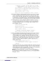
Model 250 Menu: 7. 5. Maint 5. Export
=================================
| Export Configuration |
| Start RECEIVE TEXT Download |
| to Host on Serial PORT A |
| |
| <ENTER> to Continue |
| < ESC> to Cancel |
=================================
4.
Windows TERMINAL: Tra Receive Text File....
5.
Directories - set directory to desired download directory (C:\TEMP)
6.
File Name: - Type desired File Name (for example: export1.txt)
7.
Select OK with mouse or press Enter key (dialog will be removed)
8.
Verify TERMINAL screen shows status line at bottom:
Stop, Pause, Bytes: 0, Receiving: EXPORT1.TXT
9.
Model 250 Menu:
Press
ENTER
key to start export download. NOTE: Some VT100
Emulator programs (ProComm) will send the ENTER automatically when
step 4.3 above is performed. Expect 10 minutes to export 20 sources
(500,000 bytes) at 9600 baud).
Data Transfer will begin and continue until all source, channel, channel-
source combination, and system data has been exported. The following
dialog is displayed on the projector screen during the transfer.
=================================
| Export Configuration |
| EXPORT IN PROGRESS ... wait |
| - Press ESC to Abort |
=================================
The following message is sent at the end of the export data.
##########################
# Export Complete #
# STOP Host Download Now #
# Then, Press ESC #
##########################
Summary of Contents for 250
Page 16: ...Chapter 2 System Description Model 250 Service Manual 2 9 ...
Page 43: ...Chapter 4 Optical 4 10 Model 250 Service Manual Figure 4 6 Optical Path ...
Page 55: ...Chapter 5 Optical 3 4 22 Model 100 Service Manual ...
Page 91: ...Chapter 5 Electronics 5 36 Model 250 Service Manual Figure 5 22 Scan Reversal PCB I O Diagram ...
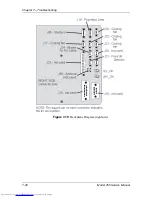
Page 131: ...Chapter 5 Electronics 5 76 Model 250 Service Manual Figure 5 44 Backplane Diagram right side ...
Page 132: ...Chapter 5 Electronics Model 250 Service Manual 5 77 ...
Page 138: ...Chapter 6 Miscellaneous Items 6 6 Model 250 Service Manual ...
Page 167: ...Chapter 7 Troubleshooting Model 250 Service Manual 7 29 ...
Page 181: ...Chapter 8 Software and Protocol 8 14 Model 250 Service Manual ...
Page 185: ...Chapter 9 Parts List 9 4 Model 250 Service Manual ...


