Chapter 3---Electrical
3-2
Model 250 Service Manual
Left/Right Orientation: When referring to the left or right in this chapter, it is with
reference to standing at the rear of the projector, facing the screen.
Connectors on subassemblies and PCBs have tabs that must be released first
before pulling on the connector. The proper procedure is to push slightly IN on
the connector, then squeeze the tab, then pull the connector out.
3.2.
Incoming Power Circuit
AC Power Cord
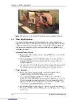
The Power Cord performs one basic function: to deliver the AC power from the
power source to the projector. It must be configured to meet the Electrical
Specifications for the region the projector will be used. The Power Cord type is
NEMA 5-20, 20A, 250A.
AC Circuit Breaker
The AC Circuit Breaker has two basic functions: one is to connect and disconnect
electrical power from the projector, the second is to protect the projector from
over-voltage conditions.
When the AC Circuit Breaker is in the OFF position, no electrical energy will
reach any part of the projector except for the AC Circuit Breaker. When the AC
Circuit Breaker is in the ON position, electrical energy goes to the AC Line Filter
and on to the Low Voltage Power Supply and Arc Lamp Power Supply. When the
AC Circuit Breaker is in the ON position but the projector has not received the
POWER ON command either from an IR Remote Control or from a PC or Laptop
computer, the projector is in Standby mode. In the Standby mode, the +5.1 V
Standby and the +24 V Standby Voltages maintain power to the CPU chips on the
System Controller PCB, the IR Detectors, and to the cooling fans.
The AC Circuit Breaker is rated at 90-264 Vac (RMS), 50/60 Hz. The current
rating is 13 Amps RMS at 90 Vac.
The power requirements of the Model 250 Projector are 200-264 Vac, 50/60 Hz,
single phase. The power consumption is rated at 2800-Watts maximum.
AC EMI Filter
The AC EMI (Electro-Magnetic Interference) Filter prevents switching noise
from a regulated power supply such as the Low Voltage Power Supply and the
Arc Lamp Power Supply, from returning to the AC power source. This switching
noise interferes with the operation of radios, televisions, and other electronic
appliances
Summary of Contents for 250
Page 16: ...Chapter 2 System Description Model 250 Service Manual 2 9 ...
Page 43: ...Chapter 4 Optical 4 10 Model 250 Service Manual Figure 4 6 Optical Path ...
Page 55: ...Chapter 5 Optical 3 4 22 Model 100 Service Manual ...
Page 91: ...Chapter 5 Electronics 5 36 Model 250 Service Manual Figure 5 22 Scan Reversal PCB I O Diagram ...
Page 131: ...Chapter 5 Electronics 5 76 Model 250 Service Manual Figure 5 44 Backplane Diagram right side ...
Page 132: ...Chapter 5 Electronics Model 250 Service Manual 5 77 ...
Page 138: ...Chapter 6 Miscellaneous Items 6 6 Model 250 Service Manual ...
Page 167: ...Chapter 7 Troubleshooting Model 250 Service Manual 7 29 ...
Page 181: ...Chapter 8 Software and Protocol 8 14 Model 250 Service Manual ...
Page 185: ...Chapter 9 Parts List 9 4 Model 250 Service Manual ...

