Chapter 3---Electrical
Model 250 Service Manual
3-5
!
+5.1V for digital components
!
+6.2V for CRT filaments
!
±15V for analog circuits
!
+80V supply used by the High Voltage Power Supply, Video Amplifier
PCB, and the Horizontal/Vertical Deflection PCB.
LVPS - Service Adjustments
There are no service adjustments for the Low Voltage Power Supply.
LVPS - Remove and Replace
Tools Needed:
#2 Posi-drive Phillips-head screwdriver
Parts Needed:
Low Voltage Power Supply - p/n 102520
To remove the Low Voltage Power Supply:
1.
Power off the projector by IR Remote or PC, and allow the cooling fans to
run until they shut off.
2.
Turn the AC Circuit Breaker to the OFF position and unplug the AC
Power Cord.
3.
Remove the front cover (see Projector Covers section 6.1).
4.
Remove the lower-right-side panel by removing the 5 Pozi-drive screws
securing it.
5.
Remove the 5 Pozi-drive screws securing the EMI Shield. Slide the shield
to the left and remove it.
6.
Remove J76 (DC Output) and J75 (AC Input) from the left side of the
Low Voltage Power Supply.
NOTE
: These connectors may be a little difficult to remove and it may be
necessary to pull the LVPS partly out of the chassis in order to get a better
grip on the connectors.
7.
Carefully slide the Low Voltage Power Supply out of the projector.
8.
Reinstall the LVPS in reverse order. After installing a new LVPS, it may
be necessary to touch-up the Timing, Geometry, Electronic Focus, ILA
®
Bias/Sensitivity, Convergence, G2, and Shading.
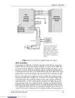
Arc Lamp Power Supply (ALPS)
ALPS - Main Functions:
!
Provides ignition power to turn the Arc Lamp ON (via the Igniter).
!
Provides steady state power to maintain the Arc Lamp operation.
Summary of Contents for 250
Page 16: ...Chapter 2 System Description Model 250 Service Manual 2 9 ...
Page 43: ...Chapter 4 Optical 4 10 Model 250 Service Manual Figure 4 6 Optical Path ...
Page 55: ...Chapter 5 Optical 3 4 22 Model 100 Service Manual ...
Page 91: ...Chapter 5 Electronics 5 36 Model 250 Service Manual Figure 5 22 Scan Reversal PCB I O Diagram ...
Page 131: ...Chapter 5 Electronics 5 76 Model 250 Service Manual Figure 5 44 Backplane Diagram right side ...
Page 132: ...Chapter 5 Electronics Model 250 Service Manual 5 77 ...
Page 138: ...Chapter 6 Miscellaneous Items 6 6 Model 250 Service Manual ...
Page 167: ...Chapter 7 Troubleshooting Model 250 Service Manual 7 29 ...
Page 181: ...Chapter 8 Software and Protocol 8 14 Model 250 Service Manual ...
Page 185: ...Chapter 9 Parts List 9 4 Model 250 Service Manual ...

