Chapter 4---Optical
Model 250 Service Manual
4-1
4.0 Optical
Contents
4.1 Arc Lamp...................................................................................................... 4-2
4.2 Optical Path .................................................................................................. 4-7
4.3 ILA
®
............................................................................................................. 4-13
4.4 Relay Lenses ................................................................................................ 4-20
4.5 Projection Lens............................................................................................. 4-20
CAUTION!
Before performing procedures in this chapter,
review the chapter on Safety at the beginning of this manual
.
WARNING!!!
When performing procedures in this chapter
that require projector covers to be off, wear high voltage gloves
(ANSI/ASTM 10,000 volt rated) when working near the CRTs, Arc Lamp,
or power supplies. Wear safety goggles (rated X5) when working
anywhere near the light path from the arc lamp or the projection lens.
Dangerous levels of ultraviolet and infrared radiation, dangerous glare, very high
temperatures (180°C to 300°C) and high internal gas pressure are present at the
Xenon Arc Lamp. The lamp is contained in a protective reflector-housing module
and should not be operated outside this housing or outside of the projector.
When replacing the Arc Lamp, replace it as an entire module, as shown in this
manual. Do not open the lamp housing or attempt to replace the Arc Lamp
inside its module! Do not touch the Arc Lamp, or any connections, when the
lamp is ignited or is arcing.
Any servicing of the Arc Lamp must remain restricted to Hughes-JVC Certified
Technicians.
Summary of Contents for 250
Page 16: ...Chapter 2 System Description Model 250 Service Manual 2 9 ...
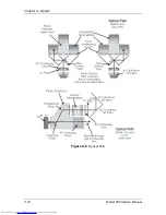
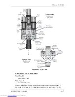
Page 43: ...Chapter 4 Optical 4 10 Model 250 Service Manual Figure 4 6 Optical Path ...
Page 55: ...Chapter 5 Optical 3 4 22 Model 100 Service Manual ...
Page 91: ...Chapter 5 Electronics 5 36 Model 250 Service Manual Figure 5 22 Scan Reversal PCB I O Diagram ...
Page 131: ...Chapter 5 Electronics 5 76 Model 250 Service Manual Figure 5 44 Backplane Diagram right side ...
Page 132: ...Chapter 5 Electronics Model 250 Service Manual 5 77 ...
Page 138: ...Chapter 6 Miscellaneous Items 6 6 Model 250 Service Manual ...
Page 167: ...Chapter 7 Troubleshooting Model 250 Service Manual 7 29 ...
Page 181: ...Chapter 8 Software and Protocol 8 14 Model 250 Service Manual ...
Page 185: ...Chapter 9 Parts List 9 4 Model 250 Service Manual ...

