Chapter 1---Introduction
Model 250 Service Manual
1-1
1.0 Introductio n
Contents
1.1 Safety............................................................................................................ 1-1
1.2 Updates......................................................................................................... 1-2
1.3 Acronyms Used ............................................................................................ 1-2
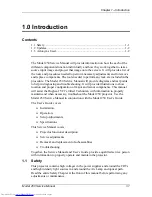
The Model 250 Service Manual will provide information on how the each of the
different components function individually and how they work together to take a
source input image and project that image onto the screen. It will provide a list of
the tools and procedures needed to perform necessary adjustments and to remove
and replace components. The tools needed to perform any task are included in the
procedure. The Model 250 Service Manual will provide diagrams and test points
to help in diagnosing and troubleshooting. It will provide illustrations to show
location and proper configuration of major and minor components. This manual
will assist the Hughes-JVC Certified Technician with information to properly
maintain and when necessary, troubleshoot the Model 250 projector. Use the
Model 250 Service Manual in conjunction with the Model 250 User’s Guide.
The User’s Guide covers
!
Installation,
!
Operation,
!
Setup Adjustments
!
Specifications
This Service Manual covers:
!
Projector functional description
!
Service adjustments
!
Removal and replacement of subassemblies
!
Troubleshooting
Together, the Service Manual and User’s Guide provide a qualified service person
with information to properly operate and maintain the projector.
1.1 Safety
This projector contains high voltages in the power supplies and around the CRTs
and high intensity light sources in and around the Arc Lamp and optical path.
Read the entire Safety Chapter at the front of this manual before performing any
adjustments or maintenance.
Summary of Contents for 250
Page 16: ...Chapter 2 System Description Model 250 Service Manual 2 9 ...
Page 43: ...Chapter 4 Optical 4 10 Model 250 Service Manual Figure 4 6 Optical Path ...
Page 55: ...Chapter 5 Optical 3 4 22 Model 100 Service Manual ...
Page 91: ...Chapter 5 Electronics 5 36 Model 250 Service Manual Figure 5 22 Scan Reversal PCB I O Diagram ...
Page 131: ...Chapter 5 Electronics 5 76 Model 250 Service Manual Figure 5 44 Backplane Diagram right side ...
Page 132: ...Chapter 5 Electronics Model 250 Service Manual 5 77 ...
Page 138: ...Chapter 6 Miscellaneous Items 6 6 Model 250 Service Manual ...
Page 167: ...Chapter 7 Troubleshooting Model 250 Service Manual 7 29 ...
Page 181: ...Chapter 8 Software and Protocol 8 14 Model 250 Service Manual ...
Page 185: ...Chapter 9 Parts List 9 4 Model 250 Service Manual ...


