Chapter 5---Electronics
Model 250 Service Manual
5-7
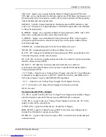
280_CLK - Square wave signal from the Raster Timing Generator PCB, with
50% duty cycle, synchronized to the horizontal sync at 280 times the frequency of
the horizontal sync. This signal is used by the System Controller PCB to properly
output shading and convergence data.
SOURCE_VALID - Signal from Raster Timing Generator PCB indicates a new
source (or valid source). A high indicates a valid stable signal and a low indicates
a change in input signal.
H_DRIVE - Square wave signal from Raster Timing Generator PCB, with a 50%
duty cycle synchronized to the selected horizontal sync.
V_DRIVE - Square wave from Raster Timing Generator PCB, with a negative
going pulse synchronized to selected vertical sync with a pulse width of about
four horizontal lines.
/FRONT_IR - command signals from the front infrared receiver.
/REAR_IR - command signals from the rear infrared receiver
H_F2V - DC voltage from the Raster Timing Generator PCB, proportional to the
horizontal frequency of the current source.
IIC CLK - IIC clock line, unidirectional clock line for control of synchronous data
transfer of data between PCBs.
IIC DATA - IIC data line, bi-directional serial data line for control of
synchronous data transfer between the System Controller PCB and the Raster
Timing Generator PCB.
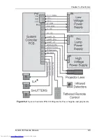
+5.1 V Stdby - from the Low Voltage Power Supply when the AC Circuit Breaker
is turned on; it supplies power to the CPU, Interlock Switches, and IR Detectors
before the projector receives the POWER ON command.
+5.1 V - from the Low Voltage Power Supply for all digital circuitry.
±15 V - from the Low Voltage Power Supply for all analog circuitry
GND - Ground
System Controller PCB - Outputs
/LV_ENA - signal to enable the Low Voltage Power Supply non-standby voltages
after the System Controller PCB receives the POWER ON command.
/FAN_ENA - signal to the Low Voltage Power Supply to turn on the +24 V stby
supply to turn on the cooling fans.
/LAMP_ENA - signal to enable the Arc Lamp Power Supply.
RGB_OVER - signal to Video Processor PCB for the On-screen Menu and /or
Internal Test Pattern for red, green, and blue.
OVERLAY - signal to the Video Processor PCB, to switch between internal and
external sources.
Summary of Contents for 250
Page 16: ...Chapter 2 System Description Model 250 Service Manual 2 9 ...
Page 43: ...Chapter 4 Optical 4 10 Model 250 Service Manual Figure 4 6 Optical Path ...
Page 55: ...Chapter 5 Optical 3 4 22 Model 100 Service Manual ...
Page 91: ...Chapter 5 Electronics 5 36 Model 250 Service Manual Figure 5 22 Scan Reversal PCB I O Diagram ...
Page 131: ...Chapter 5 Electronics 5 76 Model 250 Service Manual Figure 5 44 Backplane Diagram right side ...
Page 132: ...Chapter 5 Electronics Model 250 Service Manual 5 77 ...
Page 138: ...Chapter 6 Miscellaneous Items 6 6 Model 250 Service Manual ...
Page 167: ...Chapter 7 Troubleshooting Model 250 Service Manual 7 29 ...
Page 181: ...Chapter 8 Software and Protocol 8 14 Model 250 Service Manual ...
Page 185: ...Chapter 9 Parts List 9 4 Model 250 Service Manual ...


