Chapter 5---Electronics
Model 250 Service Manual
5-27
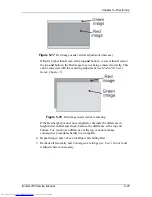
Figure 5-17
Red image needs vertical adjustment (increase).
If Red is higher than Green at the top and bottom, or lower than Green at
the top and bottom, the Red image may not being centered correctly. This
can be corrected with the centering adjustment (see Model 250 User’s
Guide, Chapter 5).
Figure 5-18
Red image needs vertical centering.
If the Red height pot does not completely eliminate the difference in
height between Red and Green, balance the difference at the top and
bottom. Too much of an difference at the top or bottom makes
convergence procedures harder to accomplish.
4.
Repeat Steps 2 and 3 above for Blue while hiding Red.
5.
Recheck all Geometry and Convergence settings (see User’s Guide) and
readjust wherever necessary.
Summary of Contents for 250
Page 16: ...Chapter 2 System Description Model 250 Service Manual 2 9 ...
Page 43: ...Chapter 4 Optical 4 10 Model 250 Service Manual Figure 4 6 Optical Path ...
Page 55: ...Chapter 5 Optical 3 4 22 Model 100 Service Manual ...
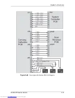
Page 91: ...Chapter 5 Electronics 5 36 Model 250 Service Manual Figure 5 22 Scan Reversal PCB I O Diagram ...
Page 131: ...Chapter 5 Electronics 5 76 Model 250 Service Manual Figure 5 44 Backplane Diagram right side ...
Page 132: ...Chapter 5 Electronics Model 250 Service Manual 5 77 ...
Page 138: ...Chapter 6 Miscellaneous Items 6 6 Model 250 Service Manual ...
Page 167: ...Chapter 7 Troubleshooting Model 250 Service Manual 7 29 ...
Page 181: ...Chapter 8 Software and Protocol 8 14 Model 250 Service Manual ...
Page 185: ...Chapter 9 Parts List 9 4 Model 250 Service Manual ...


