Chapter 5---Electronics
5-34
Model 250 Service Manual
8.
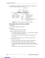
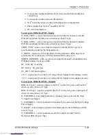
Reinstall the Convergence/Deflection PCB by lowering the right side in
first until it clears the electronic module edge, then lowering the left side
in.
NOTE:
It may be necessary to fit the top 2 fins of the heat sync over the
electronic module frame lip at the left to get enough clearance for the right
side to be installed. Carefully fit the board over the mounting screws and
slide the PCB into position. Tighten the screws and reconnect the
connectors.
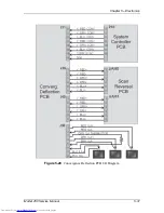
5.8 Scan Reversal PCB
Scan Reversal PCB - Main Functions
!
Reverses of scan in both horizontal and vertical axes
!
Outputs deflection waveform to the Deflection Yokes on the CRTs
!
Outputs convergence data to Convergence Yokes on the CRT
!
Horizontal width adjustment for each color (R, G &B)
!
Scan failure detection for (horizontal and vertical) deflection amplifiers
Scan Reversal PCB - Inputs
H_OUT_FLYBACK - output horizontal deflection waveform from the Horizontal
Vertical Deflection PCB (about 800 Vpp).
H_LOCK (pos.) - horizontal interlock for the yoke connectors from the
Horizontal Vertical Deflection PCB (about 5 V when closed, 15 V when open).
H_RGB (pos.) - return of horizontal deflection waveform to the Horizontal
Vertical Deflection PCB.
V_RGB (pos.) - output signals of red, green, and blue from the Vertical Amplifier
of the Horizontal Vertical Deflection PCB (about 40 Vpp).
X_RGB (pos.) - output signals of the red, green, and blue from the Horizontal
Convergence Amplifier for the X-axis from the Convergence Deflection PCB.
Y_RGB (pos.) - output signals of the red, green, and blue from the Horizontal
Convergence Amplifier for the Y-axis from the Convergence Deflection PCB.
±15 V - input power from the Horizontal Vertical Deflection PCB for the analog
circuitry.
+5.1 V - input power from the Horizontal Vertical Deflection PCB for the digital
circuitry.
From Yokes
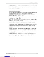
H_RGB_YOKE (neg.) - bottom of red, green, and blue horizontal deflection
yokes.
V_RGB_YOKE (neg.) - bottom of red, green, and blue vertical deflection yokes.
X_RGB_YOKE (neg.) - bottom of red, green, and blue x-axis convergence yokes.
Summary of Contents for 250
Page 16: ...Chapter 2 System Description Model 250 Service Manual 2 9 ...
Page 43: ...Chapter 4 Optical 4 10 Model 250 Service Manual Figure 4 6 Optical Path ...
Page 55: ...Chapter 5 Optical 3 4 22 Model 100 Service Manual ...
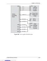
Page 91: ...Chapter 5 Electronics 5 36 Model 250 Service Manual Figure 5 22 Scan Reversal PCB I O Diagram ...
Page 131: ...Chapter 5 Electronics 5 76 Model 250 Service Manual Figure 5 44 Backplane Diagram right side ...
Page 132: ...Chapter 5 Electronics Model 250 Service Manual 5 77 ...
Page 138: ...Chapter 6 Miscellaneous Items 6 6 Model 250 Service Manual ...
Page 167: ...Chapter 7 Troubleshooting Model 250 Service Manual 7 29 ...
Page 181: ...Chapter 8 Software and Protocol 8 14 Model 250 Service Manual ...
Page 185: ...Chapter 9 Parts List 9 4 Model 250 Service Manual ...

