Chapter 5---Electronics
Model 250 Service Manual
5-35
Y_RGB_YOKE (neg.) - bottom of red, green, and blue y-axis convergence yokes.
RGB_LOCK (neg.) - interlock for red, green, and blue deflection yokes (5 V
when closed or 0 V when open).
Scan Reversal PCB - Outputs
H_LOCK (neg.) - Horizontal Interlock for the yoke connectors to the Horizontal
Vertical Deflection PCB (about 5 V when closed, 15 V when open).
FRONT/REAR - front or rear projection status line to Horizontal Vertical
Deflection PCB (front = low, rear = high).
FLOOR/CEIL - floor or ceiling status line to the Horizontal Vertical Deflection
PCB (floor = low, ceiling = high).
DEFL_OK - deflection status line from the Horizontal Vertical Deflection PCB
(high (about 2 V) = good, low = no scan).
X_RGB(neg) - current feedback signals of the red, green, and blue Horizontal
Convergence Amplifier for the x-axis to the Convergence Deflection PCB.
Y_RGB (neg.) - current feedback signals of the red, green, and blue Horizontal
Convergence Amplifier for the y-axis to the Convergence Deflection PCB.
To Yokes
H_RGB_YOKE (pos.) - top of red, green, and blue horizontal deflection yokes.
V_RGB_YOKE (pos.) - top of red, green, and blue vertical deflection yokes.
RGB_LOCK (pos.) - interlock for red, green, and blue yokes (5 V when closed or
15 V when open).
X_RGB_YOKE (pos.) - top of red, green, and blue x-axis convergence yokes.
Y_RGB_YOKE (pos.) - top of red, green, and blue y-axis convergence yokes.
Summary of Contents for 250
Page 16: ...Chapter 2 System Description Model 250 Service Manual 2 9 ...
Page 43: ...Chapter 4 Optical 4 10 Model 250 Service Manual Figure 4 6 Optical Path ...
Page 55: ...Chapter 5 Optical 3 4 22 Model 100 Service Manual ...
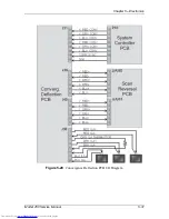
Page 91: ...Chapter 5 Electronics 5 36 Model 250 Service Manual Figure 5 22 Scan Reversal PCB I O Diagram ...
Page 131: ...Chapter 5 Electronics 5 76 Model 250 Service Manual Figure 5 44 Backplane Diagram right side ...
Page 132: ...Chapter 5 Electronics Model 250 Service Manual 5 77 ...
Page 138: ...Chapter 6 Miscellaneous Items 6 6 Model 250 Service Manual ...
Page 167: ...Chapter 7 Troubleshooting Model 250 Service Manual 7 29 ...
Page 181: ...Chapter 8 Software and Protocol 8 14 Model 250 Service Manual ...
Page 185: ...Chapter 9 Parts List 9 4 Model 250 Service Manual ...

