background image

TV/DVD COMBO

AV-20FD24

No. 52133

2003/06

COPYRIGHT © 2003 VICTOR COMPANY OF JAPAN, LTD.

AV-20FD24

SERVICE MANUAL

CONTENTS

q

SPECIFICATIONS .............................................................................................................................................. 2

q

OPERATING


INSTRUCTIONS


(APPENDIX)

q

SAFETY


PRECAUTIONS .................................................................................................................................. 3

q

SPECIFIC


SERVICE


INSTRUCTIONS .............................................................................................................. 7

q

SERVICE


ADJUSTMENTS .............................................................................................................................. 19

q

GUIDE


FOR


REPAIRING ................................................................................................................................. 25

q

STANDARD


CIRCUIT


DIAGRAM ................................................................................................................... 2-1

q

PARTS


LIST ..................................................................................................................................................... 37

TV  CATV

POWER

DISPLAY

AUDIO

SLEEP
TIMER

PLAY MODE

AUDIO

TITLE

JUMP

ANGLE

MARKER

ZOOM

 SLOW 

+

+

CH

INPUT

CH

VOL

VOL

+

CANCEL

LIGHT

MUTING

TV MENU

DVD SETUP

DVD MENU

TV/DVD

NEXT

PREV

B.SEARCH

F.SEARCH

PLAY

PAUSE/STILL

STOP

OPEN/CLOSE

SELECT

/ENTER

C.C.

1

2

3

4

5

6

7

8

9

0

RETURN

REPEATA-B RETURN

SUBTITLE

TV / DVD

Summary of Contents for AV-20FD24

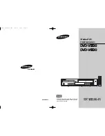
Page 1: ...INSTRUCTIONS 7 q SERVICE ADJUSTMENTS 19 q GUIDE FOR REPAIRING 25 q STANDARD CIRCUIT DIAGRAM 2 1 q PARTS LIST 37 TV CATV POWER DISPLAY AUDIO SLEEP TIMER PLAY MODE AUDIO TITLE JUMP ANGLE MARKER ZOOM SLOW CH INPUT CH VOL VOL CANCEL LIGHT MUTING TV MENU DVD SETUP DVD MENU TV DVD NEXT PREV B SEARCH F SEARCH PLAY PAUSE STILL STOP OPEN CLOSE SELECT ENTER C C 1 2 3 4 5 6 7 8 9 0 RETURN REPEATA B RETURN SU...

Page 2: ...0 mm 80 mm CD DA 120 mm 80 mm CD R RW 120 mm 80 mm Pick up 1 Lens 2 Beams System CD Wavelength 775 815 nm Maximum output power 0 5 mW DVD Wavelength 650 666 nm Maximum output power 2 0 mW Frequency Response DVD 4 Hz 22 kHz CD 4 Hz 20 kHz Audio DAC 192 kHz 24 bit GENERAL Power Source 120 V AC 60 Hz Power Consumption 115 Watts Dimensions W x H x D 574 mm x 514 5 mm x 483 mm Weight 56 1 Ibs 25 5 kg I...

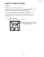
Page 3: ...ROCEDURE USE OF CONTROLS ADJUSTMENTS OR THE PERFORMANCE OF PROCEDURES OTHER THAN THOSE SPECIFIED HEREIN MAY RESULT IN HAZARDOUS RADIATION EXPOSURE TO PREVENT DIRECT EXPOSURE TO LASER BEAM DO NOT TRY TO OPEN THE ENCLOSURE VISIBLE LASER RADIATION MAY BE PRESENT WHEN THE ENCLOSURE IS OPENED DO NOT STARE INTO BEAM Location of the required Marking The rating sheet and the safety caution are on the rear...

Page 4: ...ate high impedance HV meter connected between the second anode lead and the CRT dag grounding device When servicing the High Voltage System remove static charges from it by connecting a 10k ohm resistor in series with an insulated wire such as a test probe between the picture tube dag and 2nd anode lead have AC line cord disconnected from AC supply The picture tube used in this receiver employs in...

Page 5: ...utlet try reversing the plug If the plug should still fail to fit contact your electrician to replace your obsolete outlet Do not defeat the safety purpose of the polarized plug If your unit is equipped with a 3 wire grounding type plug a plug having a third grounding pin this plug will only fit into a grounding type power outlet This too is a safety feature If you are unable to insert the plug in...

Page 6: ... the disc tray as it is closing It may cause serious personal injury 25 CONNECTING When you connect the product to other equipment turn off the power and unplug all of the equipment from the wall outlet Failure to do so may cause an electric shock and serious personal injury Read the owner s manual of the other equipment carefully and follow the instruc tions when making any connections 26 SOUND V...

Page 7: ...AL OF ANODE CAP 2 Disconnect the following connector CP801 3 Remove the CRT PCB in the direction of arrow CRT PCB Front Cabinet CP805 1 3 AV PCB DVD BLOCK Refer to Fig 1 3 1 Remove the 2 screws 1 2 Disconnect the following connectors CP104 CP301 CP302 CP401 and CP3800 3 Remove the AV PCB DVD Block in the direction of arrow Fig 1 3 AV PCB DVD Block 1 1 Front Cabinet CP104 CP301 CP302 CP401 CP3800 1...

Page 8: ...the following connectors CP2001 CP2301 and CP2302 5 Remove the 4 screws 2 6 Remove the DVD Deck in the direction of arrow B 7 Remove the 4 screws 3 8 Remove the DVD PCB in the direction of arrow C Fig 1 5 DVD PCB Deck CD 1 Deck Angle B 2 2 2 Make the sort circuit using a soldering Pick Up PCB 2 C 3 A 3 3 3 CP2001 1 Front Tray Plate CP2302 CP2301 NOTE When the installation of the DVD Deck remove al...

Page 9: ...or R Green 1 Main Frame Ass y Main Chassis Ass y NOTE 1 In case of the Main Chassis Ass y install it from 1 to 6 in order Refer to Fig 3 2 B Fig 2 2 B Main Chassis Ass y Rack Loading Move it to the direction of the arrow Main Frame Ass y 1 Check Lock 2 3 4 5 6 6 5 4 2 3 RACK LOADING MAIN GEAR RACK LOADING SPRING Refer to Fig 2 3 1 Remove the Rack L Spring 2 Press down the catcher 1 and slide the R...

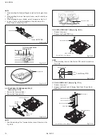
Page 10: ...4 D Lever Switch 2 5 TRAVERSE HOLDER INSULATOR F Refer to Fig 2 5 A 1 Remove the Traverse Holder 2 Remove the 2 Insulator F Fig 2 5 A Main Chassis Ass y Insulator F Black Traverse Holder Insulator F Black NOTE 1 After the installing of the Traverse Holder check if the wire is like Fig 2 5 B Fig 2 5 B Main Chassis Ass y Traverse Holder 2 6 SWITCH PCB ASS Y Refer to Fig 2 6 A 1 Remove the screw 1 2 ...

Page 11: ...B Main Chassis Ass y Relay PCB Ass y Screw Torque 4 0 5kgf cm 1 2 9 GEAR Refer to Fig 2 9 A 1 Unlock the support 1 2 Remove the Middle Gear 1 2 3 Idler Gear and Feed Gear Fig 2 9 A Middle Gear 2 Middle Gear 1 Middle Gear 3 Feed Gear Idler Gear Main Chassis Ass y NOTE 1 In case of the Idler Gear installation install correctly as Fig 2 9 B 2 When installing the Middle Gear 2 check if the Middle Gear...

Page 12: ...g Main Chassis Ass y Chassis Spring Main Chassis Ass y 2 11 FEED MOTOR Refer to Fig 2 11 A 1 Remove the 2 screws 1 2 Remove the Feed Motor 3 Remove the Motor Gear Fig 2 11 A Screw Torque 1 0 5kgf cm 1 1 Main Chassis Ass y Motor Gear Feed Motor NOTE 1 In case of the Motor Gear installation check if the valueof the Fig 2 11 B is correct 2 When installing the Feed Motor check if the cable is position...

Page 13: ...e voltage is discharged Fig 3 1 GND on the CRT Screwdriver Alligator Clip Support CRT GND on the CRT 2 Flip up the sides of the Rubber Cap in the direction of the arrow and remove one side of the support Refer to Fig 3 2 Fig 3 2 Rubber Cap CRT Support 3 After one side is removed pull in the opposite direction to remove the other NOTE Take care not to damage the Rubber Cap INSTALLATION 1 Clean the ...

Page 14: ... the IC leads completely Fig 4 2 Blower type IC desoldering machine IC 3 When IC starts moving back and forth easily after desoldering completely pickup the corner of the IC usinga tweezers and remove the IC by moving with the IC desoldering machine Refer to Fig 4 3 NOTE Some ICs on the PCB are affixed with glue so be careful not to break or damage the foil of each IC leads or solder lands under t...

Page 15: ... Solder IC Soldering Iron Supply soldering from upper position to lower position 3 Absorb the solder left on the lead using the Braided Shield Wire Refer to Fig 4 7 NOTE Do not absorb the solder to excess 5 Finally confirm the soldering status on four sides of the IC using a magnifying glass Confirm that no abnormality is found on the soldering position and installation position of the parts aroun...

Page 16: ...e pressing the Remocon Key for more than the Standard Time press the Set Key simultaneously DVD Write mode Refer to the RE WRITE FOR DVD FIRMWARE NOTE The function will only work at the DVD stop mode Do not use this for the normal servicing POWER ON total hours is displayed on the screen Refer to the PREVENTIVE CHECKS AND SERVICE INTERVALS CONFIRMATION OF HOURS USED Can be checked of the INITIAL D...

Page 17: ...selected it will blink 5 Again step through the DATA using VOL UP DOWN button until required DATA value has been selected 6 Pressing ENTER will take you back to ADDRESS for further selection if necessary 7 Repeat steps 3 to 6 until all data has been checked 8 When satisfied correct DATA has been entered turn POWER off return to STANDBY MODE to finish DATA input The unit will now have the correct D...

Page 18: ... end NOTE Do not turn off the unit on the way or push the tray by hand to close it Up Date error will happen and can not be done with the Up Date of Up Date Disc 10 Unplug the AC cord then plug it in 11 After the write set to the initializing of shipping Set to the DVD mode press both VOL DOWN button on the set and Channel button 4 on the remote control for more than 1 second 12 The INITIALIZE 9 C...

Page 19: ...ase YG6260M on the contact section of the heat sink Before applying new silicon grease remove all the old silicon grease Old grease may cause damages to the IC and Transis tor Prepare the following measurement tools for electrical adjust ments 1 Oscilloscope 2 Digital Voltmeter 3 AC Voltmeter 4 Pattern Generator 5 Multi Sound Signal Generator On Screen Display Adjustment 1 Set the VOLUME to minimu...

Page 20: ...earity reconfirm the Vertical Position and Vertical Size adjustments 1 Receive the monoscope pattern 2 Using the remote control set the brightness and contrast to normal position 3 Activate the adjustment mode display of Fig 1 1 and press the channel button 09 on the remote control to select VLIN 4 Press the VOL UP DOWN button on the remote control until the SHIFT quantity of the OVER SCAN on upsi...

Page 21: ...AV 13 Press the INPUT button on the remote control to set to the GAME mode 14 Activate the adjustment mode display of Fig 1 1 and press the channel button 54 on the remote control to select BRTCG 15 Press the VOL UP DOWN button on the remote control to set the same step numbers as the AV Fig 2 1 B A 01 OSD 15 2 13 TINT CENTER 1 Receive the color bar pattern RF Input 2 Using the remote control set ...

Page 22: ...knob of the oscilloscope until the range between white 100 and 0 is set to 4 scales on the screen of the oscilloscope 12 Press the VOL UP DOWN button on the remote control until the red color level is adjusted to 100 5 of the white level Refer to Fig 2 3 13 Press the TV DVD button on the remote control to set to the DVD mode 14 Activate the adjustment mode display of Fig 1 1 and press the channel ...

Page 23: ...forming adjustments in section 3 1 1 Receive the green raster pattern from color bar generator 2 Adjust the pair of purity magnets to center the color on the screen Adjust the pair of purity magnets so the color at the ends are equally wide 3 Move the deflection yoke backward to neck side slowly and stop it at the position when the whole screen is green 4 Confirm red and blue colors 5 Adjust the s...

Page 24: ... SPEAKER SPEAKER AC IN CRT CRT TU001 J4201 CP3800 CP401 CP302 CP101 CP802A CP8002 CP8001 CP301 J2202 J2203 J2204 AV PCB CP8502 CD8505 CP2001 CP2302 CP2301 CD802 CD3800 CD301 CD8501 CD302 VR402 VR3800 CP803A TP401 FB401 J4203 CD803 CRT CP801 CRT PCB J801 CP802B CP803B CD801 TP024 TP022 CP4201 CP104 CD751 CP751 OPERATION PCB ...

Page 25: ...on input 18 KEY2 Input 0 Voltage of the TV button input 19 AV2 Output 1 TV DVD picture signal changing output 20 AV1 Output 1 TV DVD picture signal changing output 21 IIC BUS OFF Input 0 Serial clock data stop input 22 OSD R Output 1 Red output of RGB image output 23 OSD G Output 1 Green output of RGB image output 24 OSD B Output 1 Blue output of RGB image output 25 OSD Y BLK Output 1 Fast blankin...

Page 26: ... 52133 TROUBLESHOOTING GUIDE No Yes Check display DVD OSD NO OPEN CLOSE Check connection CP2301 No Connection try again CP2301 No Change DVD LOADER DVD SECTION Check the circuit around IC2001 Yes Change IC2001 Yes No ...

Page 27: ...RE No Yes Yes No Yes No Change X4001 Check connection CP8502 Connection try again CP8502 Check IC601 and IC4202 Change IC4003 Check oscillation of X4001 Yes Change IC4002 Yes Check input signal at pins 1 3 and 5 of CP8502 Change IC2001 ...

Page 28: ...hen play check the DECK MOTOR moving Yes No Check connection CD2301 No Yes Check connection CP2001 Check DVD DECK connection bend or short Connection try again CP2001 Change DVD DECK Yes Change DVD DECK Connection try again CD2301 No After reading check INCORRECT DISC display ...

Page 29: ...ABILITY DVD MODE No Yes Connection try again CD8502 Check connection CD8502 No Yes Change DVD DECK No Yes Connection try again CD2301 CD2001 Check connection CD2301 CD2001 Change DVD DECK Check DVD DECK connection bend or short ...

Page 30: ... normal No Check the IC601 and peripheral circuit Yes Check B line No Check Q401 Q405 Q406 and peripheral circuit Yes Is the heater of CRT lighted No Check CRT TUBE and heater circuit Yes Check IC601 and peripheral circuit No Yes No Check IC101 and peripheral circuit Is the voltage at pin 28 of IC101 of 5 0V Check AT5V line and peripheral circuit ...

Page 31: ... OK No Change F3801 Yes Is the check feed back switching circuit ok Yes Check Q3803 Q3802 and peripheral circuit Is the voltage at C3815 DC175V No Check R3817 and D3808 D3809 D3815 D3816 peripheral circuit No Check Q3800 IC3800 and peripheral circuit Yes ...

Page 32: ... Yes No Is CD301 and CD302 inserted Is the voltage at pin 10 of IC351 DC 21 5V Is the voltage at pin 8 of IC351 LESS than DC 2 0V Check IC101 and peripheral circuit Yes Is the voltage at pin 11 of IC351 DC 10 3V Check P CON 12V line and peripheral circuit No Yes Is the AUDIO OUT signal at pins 7 and 11 of IC301 Check A_OUT_L A_OUT_R line and peripheral circuit No ...

Page 33: ...1 and peripheral circuit Is there a waveform at pin 7 of IC601 No Yes No Yes Is there a waveform at pin 4 of IC1501 Check IC4202 and peripheral circuit No Yes Is the voltage at pins 21 and 13 of IC601 DC 9V Check P CON 9V line Check NG MODE circuit line Is TV AV and DVD MODE of all NG No Yes Check IC601 and peripheral circuit No Yes Is the voltage at pins 36 of IC601 DC 5V Check CHROMA 5V line ...

Page 34: ... No Is the color set to normal Adjust the color No Yes Check peripheral circuit of IC601 Check the peripheral circuit of X601 Is the wavefrom at pin 35 of IC601 normal No Is the color signal received Receive the color signal Yes Yes ...

Page 35: ...orm at pins 54 55 56 and 57 of IC601 Check IC101or IC601 and peripheral circuit Check pin 25 of IC101 and IC601 peripheral circuit Check IC601 at pins 20 21 and 22 peripheral circuit Is the signal at pin 5 of IC401 normal Check DY and peripheral circuit Check IC401 and VCC 25V line No Check FB401 and peripheral circuit Check IC401 and peripheral circuit No Yes No Is there a waveform at IIC BUS lin...

Page 36: ...36 AV 20FD24 No 52133 SERVICE NOTE ...

Page 37: ...Japan 200306WPC No 52133 JVC SERVICE ENGINEERING COMPANY OF AMERICA DIVISION OF JVC AMERICAS CORP www jvcservice com US Only JVC CANADA INC Head office 21 Finchdene Square Scarborough Ontario M1X 1A7 416 293 1311 ...

Reviews: