No. 51908
21
AV-21L31
AV-25L31
Item
Measuring
instrument
Test point
Adjustment part
Description
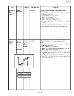
Adjustment
of
SUB
COLOR-
I
Remote
control unit
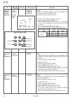
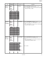
[Method of adjustment without measuring instrument]
Notes:
• Proceed to the following adjustment after having completed the ad-
justment of SUB PICTURE.
• Set PICTURE MODE (VSM) to “BRIGHT”.
1. Receive a NTSC broadcast.
2. Select
2. VC
from the SERVICE MENU.
3. Select
5. COLOR
with the MENU
&
/
^
key.
4. Set the initial setting value for NTSC 3.58 COLOR with the MENU
–/+ key.
5. If the color is not best with the initial setting value, make fine adjust-
ment until you get the best color.
6. Press the DISPLAY key twice to return to the normal screen.
5. COLOR
Adjustment
of SUB
COLOR-
II
Signal
generator
Oscilloscope
Remote
control unit
5. COLOR
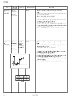
[Method of adjustment using measuring instrument]
Notes:
• Proceed to the following adjustment after having completed the ad-
justment of SUB PICTURE.
• Set PICTURE MODE (VSM) to “BRIGHT”.
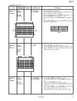
1. Receive a NTSC color bar signal (full field color bar 75% white).
2. Select
2. VC
from the SERVICE MENU.
3. Select
5. COLOR
with the MENU
&
/
^
key.
4. Set the initial setting value of NTSC 3.58 COLOR with the MENU –
/+ key.
5. Connect the oscilloscope between TP-47G and TP-E.
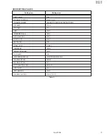
6. Adjust NTSC 3.58 COLOR to set the value
(A)
in the figure to the
voltage shown in the Table 1.
TP-47G
TP-E (
H
)
[MAIN
PWB (CRT
SOCKET)]
Mg
B
(–)
0V
(+)
R
Cy
Y
W
G
(A)
Model
A
(V
W-G
)
AV-21L31
/ME
+5V
AV-25L31
/ME
+2V
Table 1

