JVC AV 28WR2 EK/EN
8. If the picture is not the best when adjusted,
make fine adjustment until you get the best
picture.
9. Press the MENU key and memorize the
setting value.
DEFLECTION CIRCUIT ADJUSTMENT
There are 6 modes of the adjustment
(1) 50Hz mode
(1) PANORAMIC
(2) FULL
(3) REGULAR
(4)14:9 ZOOM
(5)16:9 ZOOM
(6)16:ZOOM SUB TITLE)
(2) 60Hz mode
(each aspect mode) depending upon the kind of
signals (vertical frequency 50Hz / 60Hz).
When the 50Hz PANORAMIC mode has been
established, the setting of other modes will be
done automatically.
However, if the picture quality has not been
optimized, adjust each mode again, respectively.
The adjustment using the remote control unit is
made on the basis of the initial setting values.
The setting values which adjust the screen to
the optimum condition can be different from the
Initial setting values.
Adjustments Cont’d
Adjustment Locations [AV 28WT2 EN/EK]
VIDEO/CHROMA CIRCUIT ADJUSTMENT
The setting (adjustment) using the REMOTE CONTROL UNIT is made on the basis of the initial
setting values. The setting values which adjust the screen to the optimum condition can be different
from the initial setting values.
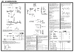
SECAM COLOUR
[Method of adjustment without measuring instrument]
1. Receive a SECAM full field colour bar signal (75% white).
2. Set the initial setting value of SECAM COLOUR with the FUNCTION
-/+ key.
3. Adjust SECAM COLOUR and bring the value of (A) of the illustration to +5V.
4. Press the MENU key and memorize the setting value.
NTSC COLOUR ADJUSTMENTS
(NTSC 3.58 COLOUR)
1. Input a NTSC 3.58MHz COMPOSITE VIDEO
signal (full field colour bar with 75% white)
from the EXT terminal.
2. Set the initial setting value of NTSC 3.58
COLOUR with the FUNCTION -/+ key.
3. Adjust NTSC 3.58 COLOUR and bring the
value of (A) of the illustration to +8V(W~B)
[AV-28WR2 EK] or 0V(W~B) [AV-28WT2 EK].
4. Press the MENU key and memorize the
setting value.
TINT ADJUSTMENTS
[NTSC 3.58 TINT]
1. Input a NTSC 3.58MHz COMPOSITE VIDEO
signal (full field colour bar with 75% white)
from the EXT terminal.
2. Select 2.V/C from the SERVICE MENU.
3. Select 6.TINT with the FUNCTION UP/DOWN
key.
4. Set the initial setting value of NTSC 3.58
TINT with the FUNCTION - or
+ key.
5. Connect the oscilloscope between TP-47B
and TP-E(***)
6. Adjust NTSC 3.58 TINT to bring the value of
(A) in the illustration to +3V [AV-28WR2 EK]
or +5V [AV-28WT2 EK] (voltage difference
between white (W) and magenta (Mg)).
7. Press the MENU key and memorize the
setting value.
Adjustment of BLACK OFFSET (SECAM) I
Measuring Instrument
Remote control unit
Adjustment Part
7. BLACK OFFSET
(R-Y)***
(B-Y)***
1. Receive a SECAM broadcast.
2. Select 2. V/C from SERVICE MENU.
3. Select 7. BLACK OFFSET with the FUNC-
TION UP/DOWN key.
4. Set the initial setting value for BLACK
OFFSET (R-Y) and (B-Y) with 4 and 7 or 6
and 9 keys of the remote control.
5. If the picture is not the best with the initial
setting value, make fine adjustment until you
get the best picture.
6. Press the MENU key and memorize the
setting value.
Adjustment of BLACK OFFSET (SECAM) II
Measuring Instrument
Signal generator
Oscilloscope
Remote control unit
Test Point
35 PIN (R-Y)
38 PIN (B-Y)
IC-101 OF MAIN PWB
Ajustment Part
7. BLACK OFFSET
(R-Y)***
(B-Y)***
1. Receive a SECAM COLOUR bar signal (full
field colour bar 75% white).
2. Select 2. V/C from SERVICE MENU.
3. Select 7. BLACK OFFSET with the FUNC-
TION UP/DOWN key.
4. Connect the oscilloscope between 35 pin of
IC-101 and TP-E (***)
5. By using 4 and 7 keys of the remote control,
adjust the BLACK OFFSET (R-Y) so that it
becomes the waveform changes from (a) to
(b) shown in the figure.
6. Connect the oscilloscope between 36 pin of
IC-101 and TP-E.
7. By using 6 and 9 keys of the remote control,
adjust the BLACK OFFSET (B-Y) so that it
becomes the waveform changes from (c) to
(d) shown in the figure.
[AV-28WR2EN/EK]
Summary of Contents for AV 28WR2 EK
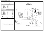
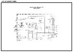
Page 4: ...JVC AV 28WR2 EK EN Main Diagram AV 28WR2EN EK ...
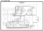
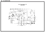
Page 5: ...JVC AV 28WR2 EK EN Main Diagram A AV 28WTEN EK ...
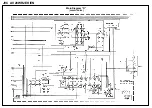
Page 6: ...JVC AV 28WR2 EK EN Main Diagram B AV 28WTEN EK ...
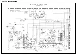
Page 7: ...JVC AV 28WR2 EK EN Main Diagram C AV 28WTEN EK ...
Page 8: ...JVC AV 28WR2 EK EN Main Diagram D AV 28WTEN EK ...
Page 9: ...JVC AV 28WR2 EK EN CRT Diagram A AV 28WTEN EK ...
Page 10: ...JVC AV 28WR2 EK EN CRT Diagram B AV 28WTEN EK ...
Page 11: ...JVC AV 28WR2 EK EN Front Control Diagram A AV 28WTEN EK ...
Page 12: ...JVC AV 28WR2 EK EN Front Control Diagram B AV 28WTEN EK ...
Page 13: ...JVC AV 28WR2 EK EN Power Deflection Diagram A AV 28WTEN EK ...
Page 14: ...JVC AV 28WR2 EK EN Power Deflection Diagram B AV 28WTEN EK ...


