
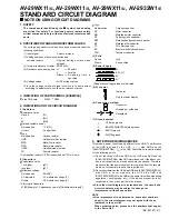
(No. 52197) 1-25
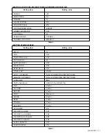
Item
Measuring
instrument
Test point
Adjustment part
Description
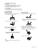
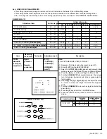
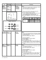
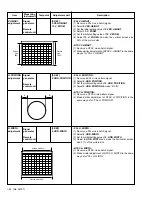
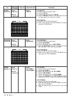
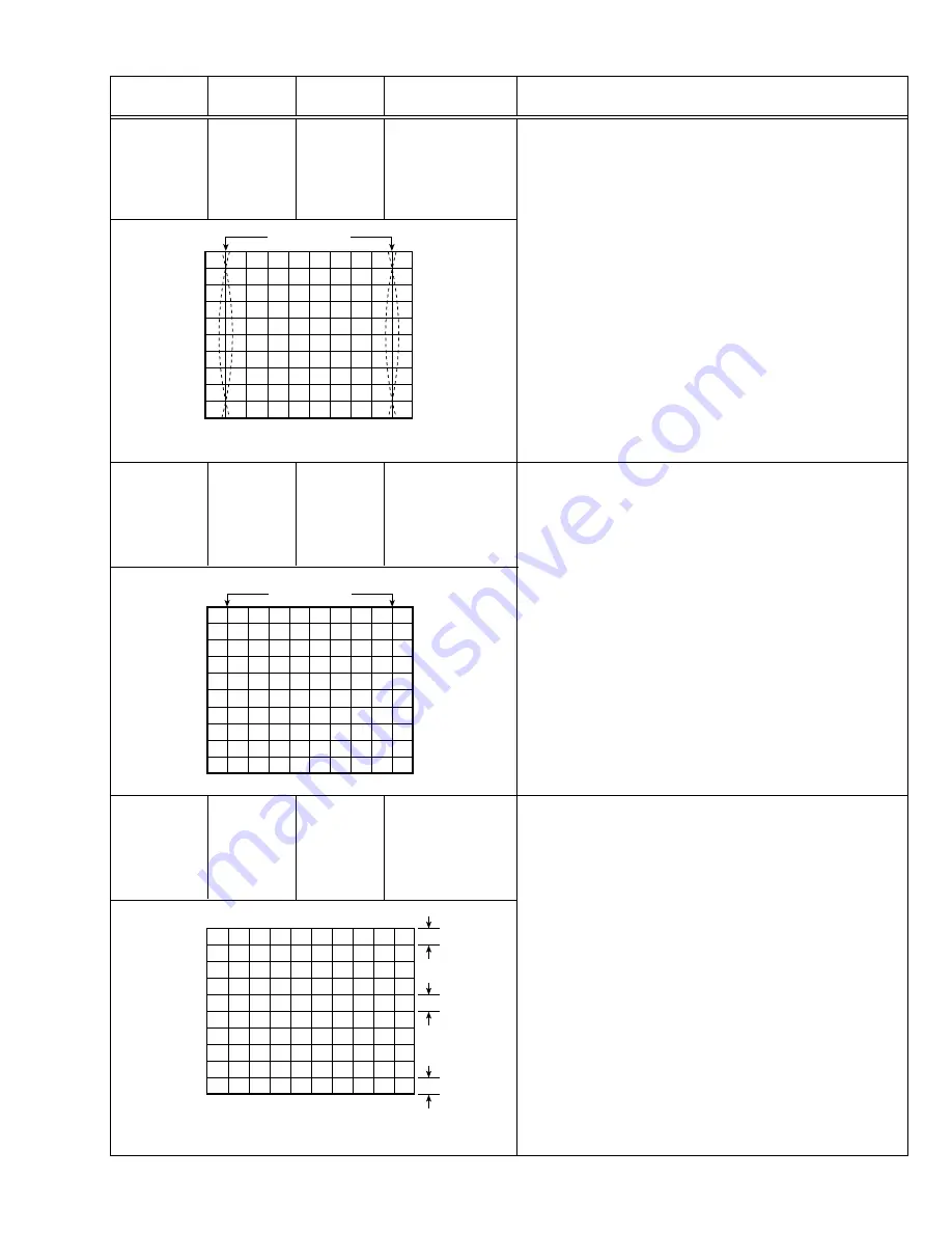
SIDE PIN
adjustment
[3. DEF]
7. EW-PIN
– PAL SIDE PIN –
(1) Receive a PAL cross-hatch signal.
(2) Select
7. EW-PIN
.
(3) Set the initial setting value of
7. EW-PIN
.
(4) Adjust
7. EW-PIN
so that the first vertical lines at the left
and right edges on the screen are straight.
– NTSC SIDE PIN –
(1) Receive a NTSC cross-hatch signal.
(2) Make similar adjustment of NTSC SIDE PIN in the same
way as for “PAL SIDE PIN”.
Signal
generator
Remote
control unit
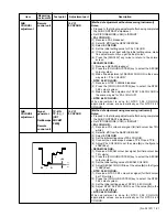
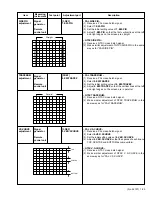
TRAPEZIUM
adjustment
[3.DEF]
8. EW-TRAPEZ
– PAL TRAPEZIUM –
(1) Receive a PAL cross-hatch signal.
(2) Select
8. EW-TRAPEZ
.
(3) Set the initial setting value of
8. EW-TRAPEZ
.
(4) Adjust
8. EW-TRAPEZ
so that the vertical lines at the left
and right edges on the screen are in parallel.
– NTSC TRAPEZIUM –
(1) Receive a NTSC cross-hatch signal.
(2) Make similar adjustment of NTSC TRAPEZIUM in the
same way as for “PAL TRAPEZIUM”.
Signal
generator
Remote
control unit
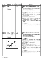
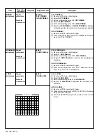
V.S-CURVE
adjustment
[3. DEF]
4. VER. SCURVE
– PAL V. S-CURVE –
(1) Receive a PAL cross-hatch signal.
(2) Select
4. VER. SCURVE
.
(3) Set the initial setting value of
4. VER. SCURVE
.
(4) Adjust
4. VER. SCURVE
so that the spaces of each line on
TOP, CENTRE and BOTTOM become uniform.
– NTSC V. S-CURVE –
(1) Receive a NTSC cross-hatch signal.
(2) Make similar adjustment of NTSC V. S-CURVE in the
same way as for “PAL V. S-CURVE”.
Signal
generator
Remote
control unit
TOP
CENTRE
BOTTOM
Parallel
Straight