background image

(No. 52197)  1-3

1.1 SAFETY  PRECAUTIONS

(1) The design of this product contains special hardware,

many circuits and components specially for safety

purposes. For continued protection, no changes should

be made to the original design unless authorized in writing

by the manufacturer. Replacement parts must be identical

to those used in the original circuits. Service should be

performed by qualified personnel only.

(2) Alterations of the design or circuitry of the products should

not be made. Any design alterations or additions will void

the manufacturer's warranty and will further relieve the

manufacturer of responsibility for personal injury or

property damage resulting therefrom.

(3) Many electrical and mechanical parts in the products have

s p e c i a l   s a f e t y - r e l a t e d   c h a r a c t e r i s t i c s .   T h e s e

characteristics are often not evident from visual inspection

nor can the protection afforded by them necessarily be

obtained by using replacement components rated for

higher voltage, wattage, etc. Replacement parts which

have these special safety characteristics are identified in

the parts list of Service manual. 

Electrical components

having such features are identified by shading on the

schematics and by (

!

) on the parts list in Service manual.

The use of a substitute replacement which does not have

the same safety characteristics as the recommended

replacement part shown in the parts list of Service manual

may cause shock, fire, or other hazards.

(4)

Don't short between the LIVE side ground and ISOLATED

(NEUTRAL) side ground or EARTH side ground when

repairing.

Some model's power circuit is partly different in the GND.

The difference of the GND is shown by the LIVE : (   ) side

GND, the ISOLATED (NEUTRAL) : (   ) side GND and

EARTH : ( 

 ) side GND. Don't short between the LIVE

side GND and ISOLATED (NEUTRAL) side GND or EARTH

side GND and never measure the LIVE side GND and

ISOLATED (NEUTRAL) side GND or EARTH side GND at

the same time with a measuring apparatus (oscilloscope

etc.).

If above note will not be kept, a fuse or any parts will be

broken.

(5) If any repair has been made to the chassis, it is

recommended that the B1 setting should be checked or

adjusted (See ADJUSTMENT OF B1 POWER SUPPLY).

(6) The high voltage applied to the picture tube must conform

with that specified in Service manual. Excessive high

voltage can cause an increase in X-Ray emission, arcing

and possible component damage, therefore operation

under excessive high voltage conditions should be kept

to a minimum, or should be prevented. If severe arcing

occurs, remove the AC power immediately and determine

the cause by visual inspection (incorrect installation,

cracked or melted high voltage harness, poor soldering,

etc.). To maintain the proper minimum level of soft X-Ray

emission, components in the high voltage circuitry

including the picture tube must be the exact replacements

or alternatives approved by the manufacturer of the

complete product.

(7) Do not check high voltage by drawing an arc. Use a high

voltage meter or a high voltage probe with a VTVM.

Discharge the picture tube before attempting meter

connection, by connecting a clip lead to the ground frame

and connecting the other end of the lead through a 10k

2W resistor to the anode button.

(8) When service is required, observe the original lead dress.

Extra precaution should be given to assure correct lead

dress in the high voltage circuit area. Where a short circuit

has occurred, those components that indicate evidence

of overheating should be replaced. Always use the

manufacturer's replacement components.

(9)

Isolation Check

(Safety for Electrical Shock Hazard)

After re-assembling the product, always perform an

isolation check on the exposed metal parts of the cabinet

(antenna terminals, video/audio input and output

terminals, Control knobs, metal cabinet, screw heads,

earphone jack, control shafts, etc.) to be sure the product

is safe to operate without danger of electrical shock.

a) Dielectric Strength Test

The isolation between the AC primary circuit and all metal

parts exposed to the user, particularly any exposed metal

part having a return path to the chassis should withstand

a voltage of 3000V AC (r.m.s.) for a period of one second.

(. . . . Withstand a voltage of 1100V AC (r.m.s.) to an

appliance rated up to 120V, and 3000V AC (r.m.s.) to an

appliance rated 200V or more, for a period of one second.)

This method of test requires a test equipment not generally

found in the service trade.

b) Leakage Current Check

Plug the AC line cord directly into the AC outlet (do not use

a line isolation transformer during this check.). Using a

"Leakage Current Tester", measure the leakage current

from each exposed metal part of the cabinet, particularly

any exposed metal part having a return path to the chassis,

to a known good earth ground (water pipe, etc.). Any

leakage current must not exceed 0.5mA AC (r.m.s.).

However, in tropical area, this must not exceed 0.2mA AC

(r.m.s.).

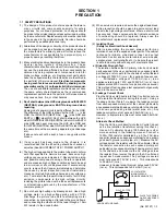
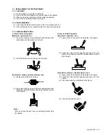
Alternate Check Method

Plug the AC line cord directly into the AC outlet (do not

use a line isolation transformer during this check.).

Use an AC voltmeter having 1000 ohms per volt or

more sensitivity in the following manner. Connect a

1500

 10W resistor paralleled by a 0.15µF AC-type

capacitor between an exposed metal part and a known

good earth ground (water pipe, etc.). Measure the AC

voltage across the resistor with the AC voltmeter. Move

the resistor connection to each exposed metal part,

particularly any exposed metal part having a return path

to the chassis, and measure the AC voltage across

the resistor. Now, reverse the plug in the AC outlet and

repeat each measurement. Any voltage measured

must not exceed 0.75V AC (r.m.s.).  This corresponds

to 0.5mA AC (r.m.s.).

However, in tropical area, this must not exceed 0.3V AC

(r.m.s.).  This corresponds to 0.2mA AC (r.m.s.).

AC VOLTMETER

(HAVING 1000

/V,

OR MORE SENSITIVITY)

PLACE THIS PROBE

ON EACH EXPOSED

METAL PART

1500

 10W

0.15

µ

F AC-TYPE

GOOD EARTH GROUND

SECTION 1

PRECAUTION

Summary of Contents for AV-2932W1

Page 1: ...9 FLAT COLOUR TELEVISION AV 29WX11 G AV 29WX11 S AV 29WX11 U AV 2932W1 E RM C1309 1H AV 2932W1 E RM C1306 1H AV 29WX11 G AV 29WX11 S AV 29WX11 U RM C1309 RM C1306 TABLE OF CONTENTS 1 PRECAUTION 1 3 2 SPECIFIC SERVICE INSTRUCTIONS 1 4 3 DISASSEMBLY 1 7 4 ADJUSTMENT 1 14 5 TROUBLESHOOTING 1 31 ...

Page 2: ...wer Consumption 177W Max 145W Avg Picture Tube Visible size 67 6cm Diagonal 54 1cm x 40 6cm H x V High Voltage 32kV 1 5kV 1 0kV at zero beam current Speaker 6 5cm 13cm Oval type 2 Audio Output 7W 7W Video Audio Input S Video 1 Mini DIN 4 pin 1 1 2 3 Y 1V p p positive negative sync provided 75Ω C 0 286V p p Burst signal 75Ω Video 1 2 3 1V p p negative sync 75Ω RCA pin jack 3 Audio 1 2 3 500mV rms 4...

Page 3: ...s approved by the manufacturer of the complete product 7 Do not check high voltage by drawing an arc Use a high voltage meter or a high voltage probe with a VTVM Discharge the picture tube before attempting meter connection by connecting a clip lead to the ground frame and connecting the other end of the lead through a 10kΩ 2W resistor to the anode button 8 When service is required observe the ori...

Page 4: ...ine textured picture in every detail Wide range voltage 110V 240V for AC power input With AUDIO VIDEO S VIDEO COMPONENT input terminals I 2 C bus control utilizes single chip ICs By means of AUTO PROGRAM the TV stations can be selected automatically and the TV channels can also be rearranged automatically Built in DIGITAL ECO MODE ECONOMY ECOLOGY In accordance with the brightness in a room the bri...

Page 5: ...UME keys RM C1306 4 3 2 1 5 6 7 8 9 11 10 12 13 14 15 16 18 17 RM C1309 1H AV 2932W1 E 1 2 3 4 5 6 7 8 9 10 11 12 13 14 MUTING key COLOUR SYSTEM key SOUND SYSTEM key DISPLAY key MENU keys TV VIDEO key OFF TIMER key PICTURE MODE key CHANNEL SCAN key RETERN key CHANNEL keys FAVORITE CH keys REVEAL key HOLD key 15 16 24 25 26 27 17 18 19 20 21 22 23 SUB PAGE key STORE key POWER key CINEMA SURROUND ke...

Page 6: ...ton CHANNEL buttons VOLUME buttons TV VIDEO buttons Remote control sensor ECO sensor POWER lamp MAIN POWER button 2 3 4 5 6 7 8 9 10 11 12 13 VIDEO 1 INPUT TERMINAL S VIDEO VIDEO AUDIO L MONO AUDIO R COMPONENT VIDEO 2 INPUT TERMINAL Y VIDEO CB CR AUDIO L MONO AUDIO R OUTPUT TERMINAL VIDEO AUDIO L AUDIO R Aerial input terminal 1 7 4 3 2 12 13 1 9 5 6 10 11 8 REAR TERMINAL ...

Page 7: ...CONTROLBASE Remove the REAR COVER Remove the CHASSIS 1 While pushing down the 2 claws E as shown in Fig 2 and pull out the CONTROL BASE in the direction of arrow F as shown in Fig 2 the control base can be removed If necessary take off the wire connector s etc 3 1 5 REMOVINGTHESPEAKER Remove the REAR COVER 1 Remove the 2 screws G as shown in Fig 1 2 Withdraw the SPEAKER backward 3 Follow the same ...

Page 8: ...ER SPEAKER 4 16 A REAR COVER D C CHASSIS BASE CONTROL BASE FRONT SIDE E F PICTURE TUBE FRONT CABINET CRT SOCKET PWB FRONT CONTROL PWB 1 2 FRONT CONTROL PWB 2 2 MAIN PWB CHASSIS BASE CONTROL BASE CLAW B CLAW B under side under side AV TERMINAL BOARD ...

Page 9: ...ANT SET are the same as those indicated in Table1 If the value is different select the setting item with the MENU key and set the correct value with the MENU key 4 Press the DISPLAY key twice to return to the normal screen 5 Receive channel setting Refer to the OPERATING INSTRUCTIONS and set the receive channels channels preset 6 User setting Check the user setting values in Table 2 and Table 3 If...

Page 10: ... 1MHz 040 500KHz 040 250KHz 040 156 25KHz 030 31 25KHz 030 3D SURROUND YES AMP TUNER NO COMPONENT YES PIP NO 16 9 YES M L delete ON Table 1 Setting item Setting content Setting value AV 29WX11 G AV 29WX11 S AV 29WX11 U AV 2932W1 E YES NO VIET YES NO YES NO 000 240 000 240 000 240 000 240 YES NO YES NO YES NO YES NO MU MA YES NO YES NO YES NO 000 240 E R A P U E R A P E R U YES NO YES NO ON OFF ERC...

Page 11: ...OMPRESS 16 9 OFF PICTURE TILT 00 AUTO SHUTOFF OFF CHILD LOCK OFF BLUE BACK ON VIDEO 2 SET VIDEO AUTO CH PRESET Refer to OPERATING INSTRUCTIONS MANUAL CH PRESET Refer to OPERATING INSTRUCTIONS LANGUAGE ENG TEXT LANGUAGE GROUP 3 AV 2932W1 E TINT Center COLOUR Center BRIGHT Center CONT Maximum SHARP Center BASS Center TREBLE Center BALANCE Center AI VOLUME ON FAVORITE CH RED PR1 FAVORITE CH GREEN PR2...

Page 12: ...SM PRESET TINT BRIGHT STANDARD SOFT COLOUR Do not adjust BRIGHT PICTURE DETAIL Service menu Setting item SERVICE MENU SETTING ITEMS Service menu Setting item 5 PRESET 1 PSNS Do not adjust 2 ACL 3 MUS 4 MAT 5 FCO 6 BPS 7 IFLH 8 VID 9 STM 10 AFCW 11 VSW 12 FFI 13 AGC 14 CL 15 AKB 16 HBL 17 BKS 18 READ STATUS 19 VNR 20 PEAK 21 IVG 22 WPL 23 SOFT CLIPPER 24 IF PLL OFFSET 25 OVERSHOOT 26 HCO 27 HP2 28 ...

Page 13: ... tweezers and alternately melt the solder at each end 2 Shift with tweezers and remove the chip part Transistors diodes variable resistors etc 1 Apply extra solder to each lead 2 As shown in the figure push the part with tweezers and alternately melt the solder at each lead Shift and remove the chip part Note After removing the part remove remaining solder from the pattern 3 3 REPLACEMENT OF CHIP ...

Page 14: ... instructions preset the following functions with the remote control unit Setting item Setting value PICTURE MODE VSM BRIGHT TINT COLOUR BRIGHT SHARP Center CONT Maximum VNR OFF AI ECO SENSOR OFF BASS TREBLE BALANCE Center 4 2 MEASURINGINSTRUMENTANDFIXTURES 1 DC voltmeter or Digital voltmeter 2 Oscilloscope 3 Signal generator Pattern generator PAL SECAM NTSC 4 Remote control unit 4 3 ADJUSTMENTITE...

Page 15: ...DER SIDE T 6 1 1 6 FRONT FRONT FRONT HVT MAIN PWB ASS Y FRONT CONTROL PWB ASS Y 1 2 FRONT CONTROL PWB ASS Y 2 2 J304 J303 J302 S804 S805 S806 S802 S803 S801 J801 CN003 CN002 A CN001 CN002 PW POWER SW W A R S901 S801 CH UP S802 CH DOWN S803 MENU S804 TV VIDEO S805 VOL UP S806 VOL DOWN 1 1 6 1 6 5 S U LOWER SCREEN TU001 J804 J801 J805 J802 J803 IC701 Z CN001 W T DEG TP E ...

Page 16: ...for service 4 Release of SERVICE MENU After completing the setting return to the SERVICE MENU by pressing the DISPLAY key then again press the DISPLAY key to return to the normal screen 1 IF For entering adjusting the setting values adjustment values of the IF circuit 2 VC For entering adjusting the setting values adjustment values of the VIDEO circuit 3 DEF For entering adjusting the setting valu...

Page 17: ...AUTO 1 CUTOFF R G V C PAL 1 VER SLOPE DEF 4 3 MENU SELECT MENU OPERATE DISPLAY EXIT SUB MENU 5 PRESET PAL B G 1 PSNS PRESET 50Hz MENU SELECT MENU OPERATE DISPLAY EXIT SUB MENU 4 VSM PRESET TINT COLOUR BRIGHT PICTURE DETAIL STANDARD MENU SELECT MENU OPERATE DISPLAY EXIT 1 PSNS 2 ACL 3 MUS 4 MAT 5 FCO 6 BPS 7 IFLH 8 VID 9 STM Setting item 10 AFCW 11 VSW 12 FFI 13 AGC 14 CL 15 AKB 16 HBL 17 BKS 18 RE...

Page 18: ...re is in focus even when the screen gets darkened IFVCO adjustment 1 IF 1 VCO CW Item Measuring instrument Test point Adjustment part Description 4 6 3 IF CIRCUIT ADJUSTMENTS Remote control unit Note Under normal conditions no adjustment is required 1 Select 1 IF from the SERVICE MENU 2 Select 1 VCO 3 Receive a broadcast signal 4 Check the characters colour of the BELOW REFERENCE displayed to yell...

Page 19: ...he 1 key to produce a single horizontal line 5 Turn the SCREEN VR fully counterclockwise then slowly turn it clockwise to where a red blue or green colour is faintly visible 6 Use the 4 and 7 or 5 and 8 keys and adjust the other 2 colours to where the single horizontal line appears white 7 Turn the SCREEN VR to where the single horizontal line glows faintly 8 Press the 2 key to return to 1 CUTOFF ...

Page 20: ...l setting value 5 If the contrast is not best with the initial setting value make fine adjustment until you get the best contrast 6 Press the DISPLAY key twice to return to the normal screen 2 VC 4 CONT WHITE BALANCE High light adjustment Signal generator Remote control unit 2 VC 2 DRIVE R 2 DRIVE G 2 DRIVE B Notes Proceed to the following adjustment after having completed the WHITE BALANCE Low li...

Page 21: ... for NTSC 4 43 COLOUR 2 VC 5 COLOUR SUB COLOURΙΙ adjustment Signal generator Oscilloscope Remote control unit 2 VC 5 COLOUR Method of adjustment using measuring instrument Notes Proceed to the following adjustment after having completed the SUB CONTRAST adjustment Set PICTURE MODE VSM to BRIGHT PAL COLOUR 1 Receive a PAL colour bar signal full field colour bar 75 white 2 Select 2 VC from the SERVI...

Page 22: ...3 TINT When adjustment is done for NTSC 3 58 TINT appropriate values are automatically set for NTSC 4 43 TINT SUBTINTΙΙ adjustment Signal generator Oscilloscope Remote control unit 2 VC 6 TINT Method of adjustment using measuring instrument Notes Proceed to the following adjustment after having completed the SUB CONTRAST adjustment Set PICTURE MODE VSM to BRIGHT NTSC 3 58 TINT 1 Receive a NTSC 3 5...

Page 23: ...nt Adjustment part Description V SLOPE adjustment Signal generator Remote control unit 3 DEF 1 VER SLOPE PAL V SLOPE 1 Receive a PAL circle pattern signal of vertical frequency 50Hz 2 Select 3 DEF from the SERVICE MENU 3 Select 1 VER SLOPE 4 Set the initial setting value of 1 VER SLOPE 5 Adjust 1 VER SLOPE to make A B 6 Press the DISPLAY key to refurn to SERVICE MENU screen NTSC V SLOPE 1 Receive ...

Page 24: ...e a PAL circle pattern signal 2 Select 5 HOR POSITION 3 Set the initial setting value of 5 HOR POSITION 4 Adjust 5 HOR POSITION to make C D NTSC H POSITION 1 Receive a NTSC circle pattern signal 2 Make similar adjustment of NTSC H POSITION in the same way as for PAL H POSITION Signal generator Remote control unit H WIDTH adjustment 3 DEF 6 HOR WIDTH PAL H WIDTH 1 Receive a PAL cross hatch signal 2...

Page 25: ...t 8 EW TRAPEZ 3 Set the initial setting value of 8 EW TRAPEZ 4 Adjust 8 EW TRAPEZ so that the vertical lines at the left and right edges on the screen are in parallel NTSC TRAPEZIUM 1 Receive a NTSC cross hatch signal 2 Make similar adjustment of NTSC TRAPEZIUM in the same way as for PAL TRAPEZIUM Signal generator Remote control unit V S CURVE adjustment 3 DEF 4 VER SCURVE PAL V S CURVE 1 Receive ...

Page 26: ...DEF 11 HOR PARALL PAL H PARALLEL 1 Receive a PAL cross hatch signal 2 Select 11 HOR PARALL 3 Set the initial setting value of 11 HOR PARALL 4 Adjust 11 HOR PARALL to optimize the parallelogram distortion NTSC H PARALLEL 1 Receive a NTSC cross hatch signal 2 Make similar adjustment of NTSC H PARALLEL in the same way as for PAL H PARALLEL Signal generator Remote control unit H BOW adjustment 3 DEF 1...

Page 27: ...uency 60Hz 2 Make similar adjustment of NTSC V HEIGHT in the same way as for PAL V HEIGHT V HEIGHT adjustment Signal generator Remote control unit 3 DEF 13 V ZOOM 2 VER HEIGHT V SLOPE adjustment Signal generator Remote control unit 3 DEF 1 VER SLOPE PAL V SLOPE 1 Receive a PAL circle pattern signal of vertical frequency 50Hz 2 Select 3 DEF from the SERVICE MENU 3 Select 1 VER SLOPE 4 Set the initi...

Page 28: ...Adjust 8 EW TRAPEZ so that the vertical lines at the left and right edges on the screen are in parallel NTSC TRAPEZIUM 1 Receive a NTSC cross hatch signal 2 Make similar adjustment of NTSC TRAPEZIUM in the same way as for PAL TRAPEZIUM Signal generator Remote control unit CORNER adjustment Signal generator Remote control unit PAL CORNER 1 Receive a PAL cross hatch signal 2 Select 9 UP CORNER 3 Set...

Page 29: ... Signal generator Remote control unit VIDEO 2 SET COMPONENT fv 50 60Hz mode VSM PRESET setting 4 VSM PRESET TINT COLOUR BRIGHT PICTURE DETAIL Remote control unit 1 Select 4 VSM PRESET from the SERVICE MENU 2 Select BRIGHT with the PICTURE MODE key 3 Adjust to reset the set values of TINT DETAIL to the values shown in the table 4 Respectively select the VSM PRESET mode for SOFT and STANDARD and mak...

Page 30: ... 7 IFLH 0 1 0 8 VID 0 1 0 9 STM 0 1 0 10 AFCW 0 1 0 11 VSW 0 1 0 12 FFI 0 1 0 13 AGC 00 01 10 11 01 14 CL 50 95 50 15 AKB 0 1 0 16 HBL 0 1 0 17 BKS 0 1 1 18 READ STATUS 19 VNR 00 63 10 20 PEAK 0 3 3 21 IVG 0 1 1 22 WPL 0 F 5 23 SOFT CLIPPER 0 3 3 24 IF PLL OFFSET 0 63 32 25 OVERSHOOT 0 3 3 26 HCO 0 1 0 27 HP2 0 1 0 28 AI VOLUME ADN 00 01 10 11 10 29 SUB BASS 6 6 0 30 SUB TREBLE 6 6 4 31 SUB TRIMME...

Page 31: ...B1 line is detected Operation of CRT neck protection circuit The main microcomputer d e t e c t s t h e p o s s i b l e abnormality at 30 msec intervals and judges the results in every 16 time Of the 16 times if NG is detected more than 9 times it is judged that there is an abnormality DITTO When an abnormality has been detected the SUB POWER is turned off While the SUB POWER is being turned off t...

Page 32: ...y notice NOTE Due improvement in performance some part numbers show in the circuit diagram may not agree with those indicated in the part list When ordering parts please use the numbers that appear in the Parts List NOTE ON USING CIRCUIT DIAGRAMS 1 SAFETY The components identified by the symbol and shading are critical for safety For continued safety replace safety critical components only with ma...

Page 33: ...N 1 N 1 N 1 N N N N N 1 SEMICONDUCTORSHAPES CONTENTS SEMICONDUCTORSHAPES 2 2 BLOCKDIAGRAM 2 3 CIRCUITDIAGRAMS MAIN PWB CIRCUIT DIAGRAM 1 2 2 5 MAIN PWB CIRCUIT DIAGRAM 2 2 2 7 CRT SOCKET PWB CIRCUIT DIAGRAM 2 9 FRONT CONTROL PWB CIRCUIT DIAGRAM 2 11 PATTERNDIAGRAMS MAIN PWB PATTERN 2 13 CRT SOCKER PWB PATTERN 2 15 FRONT CONTROL PWB PATTERN 2 16 VOLTAGECHART 2 17 WAVEFORMS 2 18 ...

Page 34: ... VIDEO FILTER PAL SECAM NTSC DEMOD TELETEXT ACQUI CHARA GEN YUV SELECT RGB MATRIX OSD INSERT SYNC SEP VIDEO DETECT QSS SOUND V DRIVE H DRIVE I2C I O PORT CPU PARABOLA DRIVE ROM RAM 29 30 15 14 13 23 26 24 13 25 19 27 16 14 10 8 7 12 SCL SDA Yout1 Cout1 MTV V MTV L MTV R Vout1 Lout1 Rout1 11 9 3 5 1 4 2 37 36 35 43 44 42 47 48 46 42 43 3 1 62 63 7 10 64 2 3 23 24 51 52 53 21 22 33 38 35 QSS OUT IF ...

Page 35: ...05X MM1492AF NCF31AZ 105X NCF31AZ 105X NCF31AZ 105X QAX0695 001Z QGF1220C2 25 NCB31CK 104X DTC323TK X DTC323TK X QQR1113 001Z MA3036 X MTZJ5 1B T2 QAU0287 001 2SC5083 L P T QQLZ014 R82 QAX0731 001 QAX0325 001 QQL244K 8R2Z QQL244K 8R2Z CH CH NCB31CK 104X QJK002 063231 QQL244K 100Z NCB31CK 104X 80 QAX0737 001 QQL244K 100Z MA3020 X MA3120 M X MA3120 M X QQL244J 101Z WJQ0003 002A CP NCB31CK 104X NCB21...

Page 36: ... 1B T2 MA3330 L X 1 2W MA3075 H X 1 2W ICP N75 Y CP QGZ5003C1 06 HV 1 2W L7812CP UN2212 X QRL039J 820 1 2W QEZ0195 475Z MTZJ15B T2 QFZ0199 184 2SA1208 ST Z1 T QRL029J 221 QQR1113 001Z BSN304 T H_DRIVE 1SS133 T2 QQR1214 001Y 1 2W 1 2W 1 2W 1 2W MA3200 M X 2SC3852A 2W QRL029J 220 MY QQR1214 001Y RGP10J 5025 T3 1 2W 1 2W TF QEHR1VM 107Z RGP10J 5025 T3 1SR35 400A T2 MY QQLZ034 460 QQL26AK 220Z MM1563D...

Page 37: ...R261 Q211 R234 R235 Y201 R262 R263 Q261 Q262 Q263 R121 R122 R123 R109 R264 R268 R272 2SA1964 DE QFK62EK 104Z MA3075 H X QRZ0107 152Z QRZ0107 152Z CE41925 001 QRZ0107 152Z EU01N T2 EU01N T2 EU01N T2 1 4WS R1 2 FR QRZ9021 561 CH CH QCS31HJ 5R0Z CH CH R1 2 R1 2 500V R1 2 RGP10J 5025 T3 2SC5248 DE QCB32HK 472Z TDA6107JF N3 RGP10J 5025 T3 2WA OMF OMR QRL029J 391 QCB32HK 472Z R1 2 QRZ9022 R47 QETM2EM 33...

Page 38: ... 123232 QSW0619 003Z QMF51E2 4R0J4 QSW0619 003Z QSW0619 003Z QRZ0111 474 QGA2501C5 04Z QQR1356 001 LH22440 T16 QNN0279 002 QNN0279 003 QNN0279 001 QNS0155 001 QQL244K 820Z P1241 04 PW QGA7901C1 02 QFZ9072 224 QAF0052 621 W CHGH0001 AB G GP1UM281QK QRE121J 561Y QFLC1HJ 103Z QSW0750 001 QSW0619 003Z QSW0619 003Z QGF1220C2 25 QSW0619 003Z LA6515 ROTATION NCB21EK 224X NCB21EK 224X NCB21EK 224X NCB21EK...

Page 39: ...R403 R404 R405 R406 R407 R408 R409 R410 R411 R412 R 4 1 3 R414 W276 W277 R425 W021 W023 W025 R480 R4 81 R482 R483 C 9 0 9 R484 R485 R486 IC901 D915 C656 R487 R006 W279 W099 R489 R490 R491 R492 R493 R494 R521 R522 R523 R524 R526 R 5 2 7 R528 R529 R530 R531 R532 W027 R534 R535 R536 R537 R538 R539 C921 R541 R542 R543 R591 R592 R593 R594 R595 R602 R603 R604 C922 R665 D651 L D655 R660 R661 R662 R663 R6...

Page 40: ...D113 D121 D122 D123 R124 D110 D112 D114 Q121 R125 Q122 D124 D201 D202 L251 R169 C121 R127 R126 C204 C211 C213 C252 C253 55 C2 C261 C262 C263 VM R101 R102 R103 R104 R105 R106 R107 R108 R109 D125 CL001 R176 W030 W031 SG101 SG102 SG103 E2 W032 Y203 Y204 E3 R142 W033 SG104 C114 R152 C123 R128 R129 W019 C267 R160 D107 R113 Q106 R211 R212 R213 R214 R215 R216 R218 R219 R220 R221 R222 R223 R224 R227 R228 ...

Page 41: ...9 R491 R801 R802 R803 R804 R805 R807 R808 R809 R810 R811 R812 R813 R814 R817 R818 D507 R513 C505 Y503 Y504 Y501 Y502 W036 C554 C551 C553 C552 T511 W050 W051 W052 FC901 Q481 Q482 R492 R497 R494 R493 R495 R496 W031 W032 W033 W040 W037 W034 W035 W039 W038 R819 R820 C814 R826 R827 R828 C660 R830 R831 C661 W055 W042 W057 W056 D491 W058 C815 W059 W063 W060 W061 W062 Y401 C487 D601 D602 R499 L401 FRONT F...

Page 42: ... 5 7 6 6 0 0 7 7 6 IC1973 1 24 9 2 11 8 3 0 0 IC1974 1 5 0 2 0 0 3 0 0 4 3 4 5 3 2 6 0 0 7 7 3 IC1975 1 10 2 2 8 9 3 0 0 4 3 2 TU1001 1 IF 0 0 2 NC 0 0 3 32V 34 2 4 LOCK 0 0 5 5V 4 9 6 BM 4 9 7 SDA 3 0 8 SCL 3 0 9 AS 0 0 10 BT 3 5 11 AGC 3 5 Q1101 E 3 3 C 0 0 B 3 4 Q1102 E 0 0 C 0 0 B 3 0 Q1103 E 0 0 C 2 8 B 0 0 Q1104 E 3 7 C 0 0 B 3 1 Q1105 E 3 1 C 8 8 B 3 7 Q1106 E 0 0 C 0 0 B 3 1 Q1107 E 0 0 C ...

Page 43: ...2Vp p H IC701 34 5 5Vp p H IC701 38 2 0Vp p H IC801 13 0 7Vp p H H IC701 53 3 6Vp p H IC801 7 1 0Vp p H IC801 23 1 5Vp p H IC801 27 1 5Vp p H IC801 37 1 5Vp p H T551 2 100Vp p T551 3 23Vp p H H T551 4 120Vp p H T551 5 120Vp p H T551 7 59Vp p H T551 9 7 0Vp p H Q522 C 1000Vp p H Q521 B 3 7Vp p Q521 C 40Vp p H Q522 B 2 5Vp p H H IC351 7 125Vp p IC351 8 120Vp p H IC351 9 160Vp p H IC701 47 1 2Vp p H ...

Page 44: ...WPC Printed in Japan No 52197 VICTOR COMPANY OF JAPAN LIMITED AV MULTIMEDIA COMPANY VIDEO DISPLAY CATEGORY 12 3 chome Moriya cho kanagawa ku Yokohama kanagawa prefecture 221 8528 Japan ...

Reviews: