
No. 52197
No. 52197
2-5
2-6
Q861
Q804
IC601
X601
C641
C824
C825
C606
R837
IC650
R838
C820
C823
C821
Q684
C813
C607
R840
R839
C833
C642
Q110
R832
R833
C608
C609
C611
C653
C610
C108
C822
R836
C831
C830
C829
C654
C650
C652
C134
C651
R656
Q307
Y101
ABL
R803
R841
K101
R155
D732
R842
C647
C640
C105
IC130
Q703
C614
R726
R708
R707
Q150
R151
R153
R150
R152
R806
R154
C747
R651
C646
Y604
C151
R652
C150
R689
R688
W-Q1
C745
CN00C
J801
Y302
J803
D655
Y601
R820
R823
C805
C682
R819
R817
R815
CF102
Q683
R691
R304
IC301
Q302
Q686
R305
Q685
R306
C655
C301
K704
C827
Q306
Q305
C656
R657
R690
C302
C303
C612
C615
C613
C616
L301
C139
Q138
R826
C304
R317
C645
R829
C644
C643
R308
C626
C807
C627
Q304
C681
C628
C629
R624
R625
C625
C630
C308
C632
C684
R695
R802
C633
C683
D101
C634
R303
J804
R301
C808
C635
C636
C801
C657
R302
J802
C802
R667
C637
R830
C638
C617
IC602
C619
C618
C620
C621
R801
C639
R602
C602
R623
C631
C604
LC601
R727
L601
C603
R603
R604
L602
C809
Q301
Y001
Y002
R804
C305
Y003
H_DRIVE
R313
C306
R309
R310
C811
R311
R831
R728
C720
CN00A
Q860
R720
C109
C812
Q103
IC701
R307
R668
R626
R627
Q662
Q663
R658
R659
Q303
R005
R712
IC801
C662
C810
R664
J805
R666
R834
R650
R654
D651
D657
R835
C817
C815
D656
C311
Q661
C313
R805
R807
Q660
R316
Q720
C142
C141
C140
C143
R147
R148
C144
R662
R661
R660
C138
C137
C136
C135
R744
R146
R143
R144
R145
C132
Q137
R142
C133
Q136
Q132
R141
R139
R140
C131
R135
R134
R133
R132
C130
CF140
CF141
CF142
R821
R312
R725
R824
Y004
C310
C750
CN001
C314
R845
R138
R137
Q134
Q130
Y130
CF131
CF130
R131
R844
Q131
Q803
R130
Q135
Q105
Q109
R117
HFB
R843
C806
C819
Q862
Q801
Q106
Q802
D733
R818
R813
R114
Q107
R809
R811
R808
R810
CF103
R115
R116
R113
R745
D804
D803
C803
R111
C804
R628
R112
R812
Y702
Q108
K706
C648
R629
Q104
D703
D817
C712
R665
L102
R669
D301
TU001
C101
C107
C104
C106
C103
C102
R102
R103
R104
R105
R106
R107
R108
Q101
L101
SF102
SF101
Q102
R109
R110
R314
R848
R701
C005
C006
R849
R004
R003
R002
R001
C003
C004
L002
C001
C002
L001
R882
R883
R101
C649
R630
R136
Q133
R880
R881
R846
R847
C307
R746
R747
C605
C834
C814
R710
R709
R713
12V
C702
D815
D816
C145
C601
R315
C312
W-Q2
W-Q3
W-YIN
R006
R663
R733
L730
CN00T
L702
C707
C732
C736
C740
C733
C731
X701
Q702
R716
R717
Q701
R715
R714
L701
D702
D801
D802
C826
R149
R653
L731
D730
D731
R655
C743
C742
Y301
C729
CN01D
CN02D
C309
R790
D701
Y701
K705
C316
Q139
CP650
R743
C315
R631
R632
R741
C706
R740
R739
R738
C711
EW
C730
D652
D653
P_ON/OFF
SCL
C713
VDRB_
VDRA+
ROTATION
R748
C705
R719
R718
R755
R756
R757
R758
3.3V_STB
R711
C658
R724
R723
R722
R721
C755
C756
R742
C725
R749
A.GND
C752
C751
C753
5V_STB
A.VCC
SDA
R730
PROTECT
R702
R703
R706
R704
C007
5V
32V
R734
9V
R705
C741
IC702
8V
C746
R731
R732
C704
C703
C734
C735
C738
C737
C739
C709
C710
C749
R737
R735
R736
C744
R750
C726
AN5277
QRK126J-121X
NCF31AZ-105X
NCF31AZ-105X
QRE121J-221Y
QRE121J-221Y
QQR1114-001Z
M52342SP
CH41171-006
QNZ0454-001
QNN0348-001
CH
NCB31CK-104X
TDA9181T/N1-X
NCB31CK-104X
QQR0582-001Z
NCB31CK-104X
QQL244K-221Z
QRL029J-101
NCF31AZ-105X
1SS268-X
QNN0349-001
NCF31AZ-105X
QNN0349-002
NJW1136GL1-W
NCB31CK-104X
MY
NCB31CK-104X
QGA2501C5-03Z
NCF31AZ-105X
MM1492AF
NCF31AZ-105X
NCF31AZ-105X
NCF31AZ-105X
QAX0695-001Z
QGF1220C2-25
NCB31CK-104X
DTC323TK-X
DTC323TK-X
QQR1113-001Z
MA3036-X
MTZJ5.1B-T2
QAU0287-001
2SC5083/L-P/-T
QQLZ014-R82
QAX0731-001
QAX0325-001
QQL244K-8R2Z
QQL244K-8R2Z
CH
CH
NCB31CK-104X
QJK002-063231
QQL244K-100Z
NCB31CK-104X
80%
QAX0737-001
QQL244K-100Z
MA3020-X
MA3120/M/-X
MA3120/M/-X
QQL244J-101Z
WJQ0003-002A
CP
NCB31CK-104X
NCB21EK-224X
MA3330/L/-X
MA3330/L/-X
NCB21HK-104X
NCB21HK-104X
NCB21HK-104X
AT24WC0829VX71G
1%
CH
CH
NFV91CJ-104X
12MHZ
∗
2
∗
7
X
X
4.7/50
100/16
.01
X
100
120
1
100/16
1
∗
2
.01
X
22/50
X
∗
5
390
270
X
X
X
.22
X
X
470/16
75
.01
.01
.01
.22
1
1/50
.01
100/50
2.2
X
BW
33K
0
470
∗
3
0
.47
.33
.0047
X
X
4.7K
4.7K
4.7K
X
X
X
X
X
75
X
.047
6.8k
.1
X
X
6.8k
X
X
27k
.047
X
∗
3
0
100
100
220/16
100
100
100
X
∗
2
1K
2.2K
∗
2
∗
6
2.2K
∗
6
5.6K
.22
.1
.01
X
X
.22
2.2
100k
.1
X
X
X
X
X
220
.01
∗
5
100
.01
.1
75
.0022
.1
100
.033
1
.047
∗
1
220/16
.022
.0022
100
100
.47
.1
.01
4.7/50
10/50
15K
75
4.7/50
33/16
4.7/50
5.6K
2.2K
1
4.7/50
4.7/50
10/50
X
2.2K
10/50
X
4.7/50
2.2K
4.7/50
X
X
X
X
X
75
100/50
X
X
47K
4.7/50
X
X
100K
X
X
X
X
X
.01
∗
2
0
0
75
.01
X
X
.1
47K
47K
12K
2.2K
10K
47/25
∗
1
1K
10/50
X
∗
10K
X
1K
1K
X
X
X
X
∗
5
27K
100
10/50
2.2k
X
X
5.6k
10K
10K
X
∗
3
5.6k
1/10
1/10
X
X
∗
1
X
75
75
∗
1
X
∗
2
.01
.01
.01
10/50
1K
3.3K
.022
33k
68k
10k
.01
.01
.01
47/25
10K
10K
470
22
820
.01
∗
1
560
100/16
∗
1
∗
1
1.8K
2.2K
1.5K
.01
560
1.8K
1.5K
2.2K
.01
QAX0696-001Z
QAX0697-001Z
2.2k
X
10K
2.2k
X
X
X
X
1K
470
10K
∗
5
∗
2
0
QAX0642-001Z
X
470
2.2K
∗
5
∗
2
4.7K
∗
5
∗
1
∗
5
10k
820
.1
∗
2
∗
2
∗
3
2.2k
2.2k
1k
∗
5
390
390
82k
82k
QAX0639-001Z
470
X
1K
1M
X
X
10/50
1K
10/50
10K
X
100K
BW
∗
1
X
1K
∗
2
X
47/16
X
QQL244K-180Z
X
.0047
.01
.0047
18p
.0047
.0047
6.8K
2.7K
180
22
100
4.7k
2.2k
∗
5
2.2k
X
X
220
100
.0022
33/16
470
220
3.9K
220
220
.1
470/16
8.2
.01
10/50
8.2
180
470
10
X
1K
4.7K
∗
2
2K
10K
2.2K
10K
33p
33k
10k
X
180p
4.7K
4.7K
100
10/50
X
X
.01
X
X
X
X
X
75
10k
27K
BW
10
1000/6.3
100/16
1/50
2.2/50
.1
.22
∗
2
10K
10K
∗
2
100
100
10
.1
470
100K
100
∗
3
∗
3
100K
100/16
.1
X
47/16
X
27
∗
3
X
X
X
∗
5
BW
X
.047
X
X
100
.22/25
100
100
10k
.1
.1
2.2M
X
220
220
100
100
4.7K
4.7K
100
X
220
220
220
220
X
X
0
680p
1.8M
.1
.1
.1
22K
100
100
1K
1K
.01
390
1K
.1
100p
100
3.9K
33p
33p
.0022
2.2n
.1
1/50
.1
470/16
.22
10/50
2.7k
100K
33K
2200p
0
180p
R2
L2
L1
SW1
Y1
CR
LOUT1
LOUT2
ROUT2
R1
L2
COUT1
R2
Y2
CR
Y2
OFF_MUTE
ROUT1
VOUT2
V1
L1
Y1
ROTATION
ECO
VOUT2
KEYIN
YOUT1
YOUT1
REMOTE
CB
SCL
SDA
LED
SCL
CB
R1
C1
SW1
SDA
ROUT2
V
A_OUT_L
A_OUT_R
B.MUTE
A.GND
COUT1
BASS
LOUT2
C1
V1
A.GND
EW
MSPRESET
SCL
V
ECO
SDA
A_OUT_R
OFF_MUTE
SDA
PROTECT
SCL
SCL
ROUT1
R
P_ON/OFF
SDA
LOUT1
MSPRESET
YOUT1
PROTECT
SCL
P_ON/OFF
A_OUT_L
EW
VDRB_
VDRA+
SCL
SDA
REMOTE
KEYIN
ROTATION
LED
R
VDRA+
VDRB_
B.MUTE
BASS
L
L
SDA
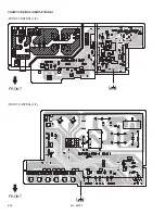
FRONT
CONTROL PWB
CN001
FRONT CONTROL PWB
CN00A
VIDEO-1
INPUT
COMPONENT
(VIDEO-2)
INPUT
OUTPUT
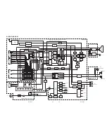
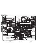
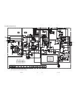
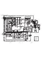
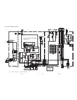
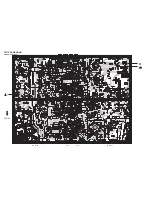
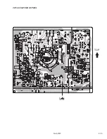
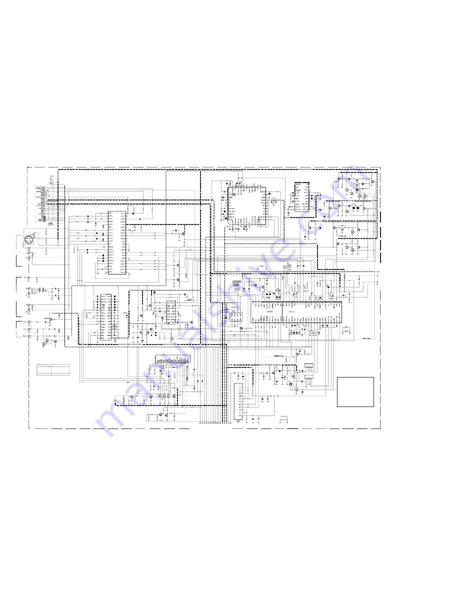
MAIN PWB ASS'Y (1/2)
SCH-1182A-H2 (AV-29WX11/G)
SCH-1183A-H2 (AV-29WX11/S)
SCH-1184A-H2 (AV-2932W1/E)
SCH-1185A-H2 (AV-29WX11/U)
CRT SOCKET PWB
CN00T
∗
DIFFERENCE LIST (
∗
PART)
IC701
SCH-1182A-H2
SCH-1183A-H2 TDA9386N23I1215
SCH-1185A-H2
SCH-1184A-H2 TDA9365N24I1291
: NON MOUNT (OPEN)
: DTC323TK-X
: UN2212-X
: MA111-X
: 2SA1530A/QR/-X
: 2SC3928A/QR/-X
: BUS WIRE
∗
3
∗
6
: KTC3199/YG/-T
∗
7
∗
5
∗
1
∗
2
BW
X
: NRSA63J-0R0X
0
NOTE
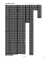
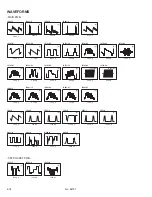
NOTES) 1. Please refer to page 2-17 for voltages of this circuit diagram.
2. Please refer to page 2-18 for waveforms of this circuit diagram.
MAIN PWB CIRCUIT DIAGRAM (1/2)
CIRCUIT DIAGRAMS