
No. 52197
No. 52197
2-7
2-8
: OPTION (OPEN)
: MTZJ7.5S-T2
: 1SR124-400A-T2
: MA111-X
: 2SA1530A/QR/-X
: 2SC3928A/QR/-X
: BUS WIRE
∗
3
∗
7
: 2SC2785/JH/-T
∗
8
∗
6
∗
1
∗
2
BW
X
: NRSA63J-0R0X
0
NOTE
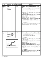
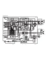
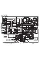
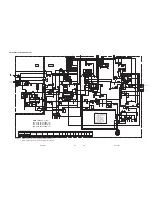
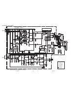
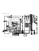
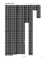
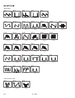
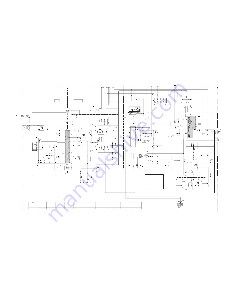
NOTES) 1. Please refer to page 2-17 for voltages of this circuit diagram.
2. Please refer to page 2-18 for waveforms of this circuit diagram.
C532
D917
D966
K955
C917
D965
C955
R953
R972
C959
C957
T901
R965
R963
R964
Q953
R973
C912
L541
R970
C985
C919
K956
R531
K951
R955
D911
R571
CNDEG
K952
C909
R406
IC974
PC901
TH901
D952
C952
C966
LF901
IC480
C978
C953
D553
D906
C529
CN00U
C404
C979
R904
IC901
L952
R913
C571
L480
R409
C409
IC461
D907
D950
D914
D919
R414
C916
D401
C401
R425
R401
CP952
K953
C920
D956
C969
C960
R494
R530
R487
C981
R915
Q480
D902
D408
D915
D903
C521
D916
C983
D970
R484
C922
D525
R485
D964
R912
D592
D957
C484
R483
C485
R493
CP951
R407
CN0HV
R916
C901
R480
C593
C911
R486
IC973
C591
Q592
R490
Q952
R489
R958
R546
C483
C915
D920
Y906
Q955
Y522
C527
Q572
R491
R492
R481
R482
C480
R971
D594
C537
R962
R968
C572
Q591
C481
R575
R547
R533
Y903
Y571
R585
Y904
K906
Y901
Y572
C961
Y902
Q521
D909
C968
D921
C965
K901
R957
R542
R545
R951
R593
R952
C964
D908
R966
Q901
C975
C980
R974
C986
C982
K902
D912
C921
C970
C471
R405
R908
C422
R911
R921
R960
C540
C535
C403
C408
C539
R411
R907
R534
C963
D541
D593
D955
C971
L951
L401
R535
IC972
K905
C984
Y907
Y908
R415
C520
C913
K904
R959
C967
R902
R903
IC975
R956
L522
D961
D402
R416
C974
D959
C972
L953
C976
L954
C962
C977
R954
D958
R527
R523
D480
C542
CN01V
CN02V
R413
D971
R543
C407
C910
CN02H
R969
C550
C412
D550
R967
CN01H
D968
Q954
RY901
D969
R905
T551
CN02Z
T521
R595
Q951
R906
Q522
K903
R521
R522
C522
C523
R526
R914
C905
R524
C992
C907
C973
C991
R402
C402
R403
CN01Z
R404
R408
IC951
C413
K954
C536
C954
D953
D913
R532
C956
R991
D524
CN00S
D595
R539
R538
Q523
Q524
R537
R592
R536
C538
D596
R577
R576
Q571
R574
R573
R572
D551
C575
C573
Q574
Q575
R541
Q573
R591
C533
C574
R582
D901
R581
R584
IC401
R528
C530
R579
R580
R529
R594
C541
R583
R578
R568
R567
R566
R565
R564
C565
C592
C525
D562
C531
D561
C534
C564
C563
Y561
C566
C524
D554
D523
D521
D522
C526
C411
R961
C528
C918
D954
CP953
D960
C958
C903
C904
C993
R410
C406
T561
R561
R562
C561
L561
R563
D405
R412
CN00W
L523
8V
C902
ROTATION
PROTECT
P_ON/OFF
ABL
R478
3.3V_STB
5V_STB
12V
9V
H_DRIVE
32V
R479
A.GND
A.VCC
HFB
5V
SDA
SCL
VDRA+
VDRB_
EW
QCB32HK-561Z
1SS133-T2
MA3047/L/-X
QQR1214-001Y
QCB32HK-181Z
QCB32HK-471Z
1/2W
1/2W
QCZ0364-561
QQS0226-001
!
1/2W
1/2W
QQL244K-220Z
MY
QCZ0325-391
QRG01GJ-330
RGP10J-5025-T3
QQZ5003C1-02
QCZ0325-102
MM1565AF-X
PC123F2
!
QAD0145-2R3
QCB32HK-471Z
QQR1356-001
!
!
!
UPC358G2-XE
NCB21HK-104X
QEHQ1VM-228
RGP10J-5025-T3
MTZJ27B-T2
QENC2AM-225Z
QGA2501C5-06Z
1/2W
STR-F6256S-F7
QRZ9017-100
!
QQR1138-001
JLC1562BF-X
MTZJ33B-T2
RGP10J-5025-T3
1SS133-T2
1/2W
RGP10J-5025-T3
ICP-N38-Y
CP
QQR1214-001Y
QCZ0122-561
31DF6N-FC5
QEZ0203-227
QRL039J-330
2SD1913( RS)
MTZJ33B-T2
MTZJ39B-T2
MTZJ15B-T2
MTZJ9.1B-T2
MA3330/L/-X
1/2W
MA3075/H/-X
1/2W
ICP-N75-Y
!
CP
QGZ5003C1-06
HV
1/2W
L7812CP
UN2212-X
QRL039J-820
1/2W
QEZ0195-475Z
MTZJ15B-T2
QFZ0199-184
2SA1208/ST/Z1-T
QRL029J-221
QQR1113-001Z
BSN304-T
H_DRIVE
1SS133-T2
QQR1214-001Y
1/2W
1/2W
1/2W
1/2W
MA3200/M/-X
2SC3852A
2W
QRL029J-220
MY
QQR1214-001Y
RGP10J-5025-T3
1/2W
1/2W
TF
QEHR1VM-107Z
RGP10J-5025-T3
1SR35-400A-T2
MY
QQLZ034-460
QQL26AK-220Z
MM1563DF-X
QQR1113-001Z
MY
QQR1113-001Z
1/2W
QRF154K-2R2
3W
QRL039J-393
PQ090RD01SZ
1/2
QRE121J-120Y
MTZJ75-T2
MY
QQL244J-5R6Z
QQL26AK-820Z
1/2W
MTZJ5.1A-T2
QRL039J-103
QRL039J-121
MTZJ4.3A-T2
NRSA02J-0R0X
1/2W
QCS32HJ-560Z
2W
QRT029J-2R2
NCF21HZ-334X
QSK0061-001
!
QQH0169-001
!
QQR1229-001
2SA1013/RO/-T
1/4W
H.OUT
2SD2634-YD
QQR1214-001Y
CC
CC
QRL029J-271
QRL039J-473
AC400V
QCZ9015-102Z
QRL039J-121
QCZ9079-471
!
AC400V
QCZ9079-102
!
SE135N
CC
QQR1214-001Y
MY
RGP10J-5025-T3
RGP10M-5010-T3
QRZ9017-4R7
!
QETN1VM-107Z
1W
QRZ0057-825
!
QGA2501C5-05Z
QRZ0225-2R2
EU2-T3
V_DAF
1/2W
V_DAF
1/2W
QRA14CF-1202Y
QEHR1EM-108Z
MY
GSIB460
LA78041
QRZ9021-1R0
QCB32HK-561Z
QRZ9021-1R0
1/2W
1/2W
1/2W
1/2W
1/2W
1/2W
QETM2CM-227
QFZ0196-123
QEHR1EM-108Z
QCB32HK-561Z
RGP10J-5025-T3
RGP10J-5025-T3
RH3G-F1
31DF6N-FC5
QFP32JJ-223
NCF21HZ-334X
QRL029J-223
QFZ0199-204
QCB32HK-103
RU30A-F1
ICP-N38-Y
!
CP
AC400V
QCZ9015-102Z
AC400V
QCZ9015-102Z
QCZ9079-471
!
QFLC2AJ-683Z
1/2W
1N4003-T2
1/2W
QGA7901C1-02
QQR1243-001
QFZ9075-104
!
QCB32HK-222Z
560P
X
470p
1.5K
1.8K
560p/2kV
470p
0
3.3K
10K
∗
1
3.3K
X
15K
470p
X
1.8K
QQR1214
-001Y
33
X
X
1000P/2KV
4.7K
ERC30-02L38
470p
100/16
0.1
2200/35
2.2/250
X
X
220
BW
X
X
X
0
12
4.7/50
33/50
82K
12K
560p
1000/16
220/160
330
X
33K
.001
82K
∗
3
X
47/35
220/16
5.6K
22/100V
X
12K
12K
BW
X
82K
22/50
22K
X
150k
X
680
47/25
100/35
2.7K
100/16
1K
∗
1
1.2K
82
8.2K
4.7/250
X
∗
1
X
X
5.6K
8.2K
22K
5.6K
10/50
18K
∗
∗
680
330
X
X
X
∗
X
X
X
X
X
X
47/16
X
220/16
BW
47/35
5.6
82K
22
22K
3.3K
2.2K
47/25
22K
220/16
100/16
22
.1
47/16
0.047
100/16
10/50
6.8K
10K
1000/35
1.5k
X
390
.1
X
100/35
X
X
330
x
∗
470/16
∗
470p
46
∗
.1
X
X
X
∗
0.068
82
1/50
2.2
39K
12
X
∗
3
1M
.1
BW
47/25
X
10/50
47/25
15
10k
120
X
X
1.2
470
1000p
X
2.2
0
X
47K
X
∗
3
∗
1
∗
3
.1
X
2.2k
1.5
470
100K
.0033
.022
270
47K
.001
120
∗
X
.001
X
10n
0
X
6.8K
.056/100
.01
X
4.7
100/35
8.2M
X
∗
∗
∗
∗
∗
∗
2.2
∗
∗
∗
X
X
X
X
X
X
X
X
X
180K
X
12K
1000/25
X
X
X
X
1
560p/500
X
X
1
18k
10/250
X
X
X
X
X
X
X
X
220/160
X
1000/25
X
560P
X
X
X
X
∗
.022
22k
0.20
.01/500
∗
3
1000/16
.001
.001
4.7K
X
X
X
X
X
X
1
100
100
X
H_DRIVE
5V
A.VCC
3.3V_STB
8V
9V
3.3V_STB
9V
32V
H_DRIVE
A.VCC
32V
STB
STB
8V
9V
9V
5V
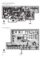
FRONT
CONTROL PWB
CN00W
L01
QQW0150-001
DEG COIL
CRT SOCKET PWB
CN00U
ADJ. CONNECTOR
DEF YOKE
!
!
!
!
!
!
!
!
LIVE
ISOLATED
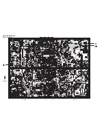
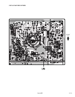
MAIN PWB ASS'Y (2/2)
SCH-1182A-H2 (AV-29WX11/G)
SCH-1183A-H2 (AV-29WX11/S)
SCH-1184A-H2 (AV-2932W1/E)
SCH-1185A-H2 (AV-29WX11/U)
∗
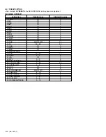
DIFFERENCE LIST (
∗
PARTS)
C907
C520
C524
R533
R534
R535
R536
R537
R538
R539
C537
C538
D593
D594
D595
D596
Q523
Q524
SCH-1182A-H2
SCH-1183A-H2
QEZ0649-337
SCH-1184A-H2
QEZ0633-337
SCH-1185A-H2
QEZ0649-337
X
QFZ0196-562
QRZ9017-4R7
NRSA02F-362X NRSA02F-6341X
10K
18K
120K
27K
47/35
4.7/50
∗
6
∗
7
∗
3
∗
3
∗
8
∗
2
QFZ0196-282
QFZ0196-282
X
X
X
X
X
X
X
X
X
X
X
X
X
X
X
MAIN PWB CIRCUIT DIAGRAM (2/2)