No. 52003
AV-36F703
AV-36F713
AV-36F803
24
Item
Measuring
instrument
Test point
Ad justment part
Description
V. HEIGHT and V. CENTER adjustment of in the 4:3 size should
be finished.
V. HEIGHT
V. LINEARITY
adjustment
(16:9)
Signal
generator
Remote
control unit
D08:V. SIZ E+-
D14:V. LINE+-
5. Receive a black -and- white signal (color off).
6. Select
16:9
aspect mode with remote control unit.
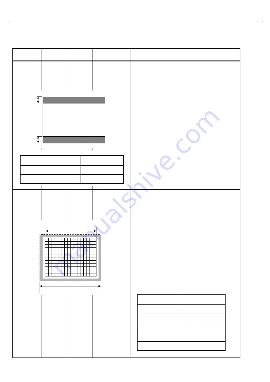
7. Confirm that the V-blanking of the upper bottom is equal, and
its width is about
67mm
.
8. If the condition is not c orrect, enter to the SERVICE MENU.
9. Adjust the
D08:V. SIZ E+-
and
D14:V. LIN+-
to become the
blanking width to
67mm
.
10. Press the EXIT key to twice to return the normal screen.
(NOTE)
When you change the vertic al deflection adjustment value in
the regular mode (4:3), readjust the 16:9 mode from beginning.
V. HEIGHT and V. POSITION adjustment of in the 4:3 s iz e should
be finished.
H. POSITION
H. SIZ E &
SIDE PIN
adjustment
(4:3)
Signal
generator
Remote
control unit
D03:H.POSI.
D15:H. SIZE
D23:EW PARA
D19:EWCR TOP
D21:EWCR BMT
11. Receive a cross hatc h signal.
12. Enter to the SERVICE MENU.
13. Select the
D03: H. POSI
from 2.DEF (D) item.
14. Adjust by
D03:H. POSI
to become same size at both s ide.
15. Then adjust the horizontal size of the vis ible screen at both
side of right-and-left to 90% with the
D15:H.SIZE
.
16. And adjust the vertical line at both side to become straight line
by
D23:EW PARA
.
17. Confirm that the linearity of vertical line and horizontal size.
18. If it is necessary, readjust 14
~
17.
19. Press the EXIT key twice to return to the normal screen.
(NOTE)
If it is not straight the vertic al line at the upper and bottom
corner, adjust the upper and bottom corner pin still more by
D19:EWCR
TOP
and
D21:EWCR BT M
.
Picture size
100%
Screen size
90.0%
B
B
[B=B]
Ad justment item
Initial setting value
D08 V. SIZ E+-
-30
D14 V. LIN+-
00
Ad justment item
Initial setting value
D03 H. POSI
22
D15 H. SIZE
30
D23 EW PARA
37
D19 EWCR TOP
08
D21 EWCR BMT
08


