1-50 (No.YA318)
SUB COLOR /
SUB TINT /
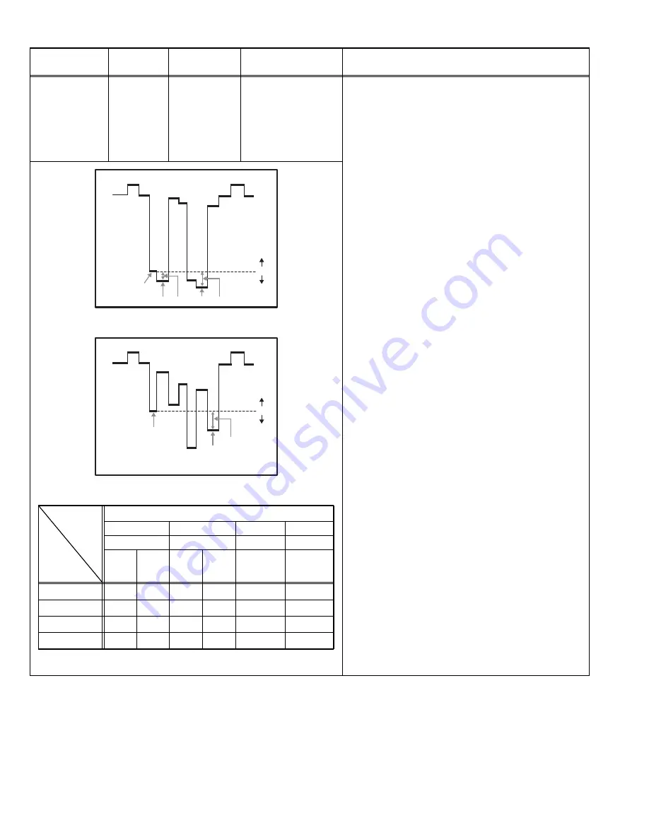
B-Y GAIN
adjustment (2)
Signal
generator
Oscilloscope
Remote
control unit
TP-R
[R CRT
SOCKET PWB]
TP-B
[B CRT
SOCKET PWB]
TP-E (GND)
[1.PICTURE/SOUND]
S01 : COLOR
S02 : TINT
S07 : B-Y
[ Method of adjustment with measuring instrument ]
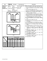
(1) Receive NTSC color bar signal (include 75% white).
(2) Select STANDARD mode with [VIDEO STATUS]
key.
(3) Connect the oscilloscope to TP-R.
(4) Select 1.PICTURE/SOUND from SERVICE MENU.
(5) Select < S01 > (COLOR) and < S02 > (TINT).
(6) Adjust < S01 > and < S02 > to be following setting
value A[V]. (Refer to the table)
(7) Press [MUTING] key to memorize the set values.
(8) Select THEATER mode with [VIDEO STATUS] key.
(9) Adjust < S01 > and < S02 > to be following setting
value B[V] same as above. (Refer to the table)
(10) Press [MUTING] key to memorize the set values.
(11) Select STANDARD mode with [VIDEO STATUS]
key.
(12) Connect the oscilloscope to TP-B.
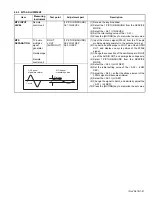
(13) Adjust < S07 > (B-Y) to be setting value C[V]. (Refer
to the table)
(14) Press [MUTING] key to memorize the set values.
(15) Select THEATER mode with [VIDEO STATUS] key.
(16) Adjust < S07 > to be setting value D[V]. (Refer to the
table)
(17) Press [MUTING] key to memorize the set values.
(18) Confirm that LOW-LIGHT is not different after
adjusting. If it is green or magenta, to adjust LOW-
LIGHT again. If adjust again, to set offset value
again.
(19) Input 480i component color bar signal from
COMPONENT VIDEO terminal.
(20) Repeat steps 2 to 17 above.
(21) Input 480p component color bar signal from
COMPONENT VIDEO terminal.
(22) Repeat steps 2 to 17 above.
(23) Input 1080i component color bar signal from
COMPONENT VIDEO terminal.
(24) Repeat steps 2 to 17 above.
Fig.1
Fig.2
Table
Item
Measuring
instrument
Test point
Adjustment part
Description
W
Y
R
(W-Y)
(W-R)
0
(-)
(+)
W
(W-B)
B
0
(-)
(+)
Setting item
Signal
STANDARD
THEATER
STANDARD
THEATER
A
B
C
D
Setting value
[V]
S01
(W-R)
S02
(W-Y)
S01
(W-R)
S02
(W-Y)
S07
(W-B)
S07
(W-B)
NTSC
+26
1080i
+15
480p
+19
480i
+23
+11
+5
+11
+11
+15
+5
-6
+5
+3
+4
-3
-4
+4
-20
-24
-15
+8
-25
-40
-13
Summary of Contents for AV-48P776/H
Page 1: ......
Page 92: ... No YA318 2 4 ...
Page 135: ...2 47 No YA318 PATTERN DIAGRAMS MAIN PWB PATTERN SOLDER SIDE ...
Page 136: ... No YA318 2 48 FRONT ...
Page 137: ...2 49 No YA318 MAIN PWB PATTERN PARTS SIDE ...
Page 138: ... No YA318 2 50 FRONT ...


