AV-N29304
AV-N29430
(No.52129)1-17
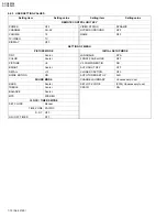
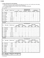
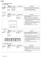
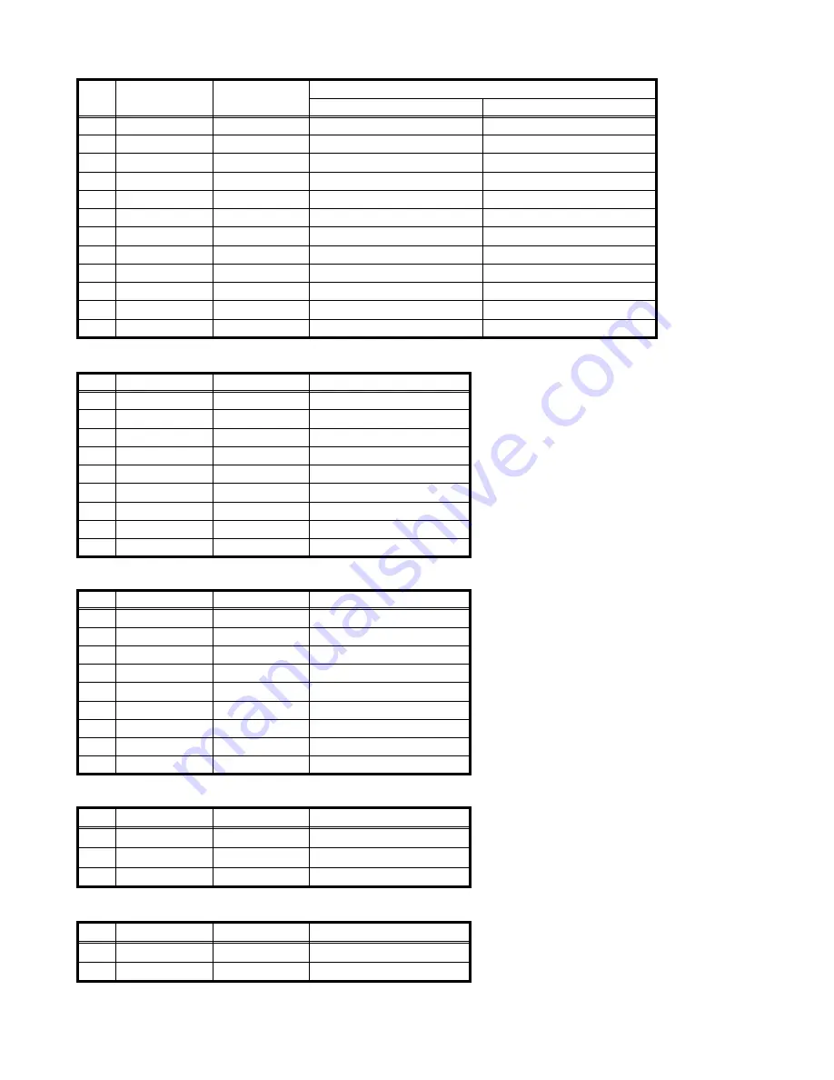
3.5.2 [2.DEF]
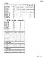
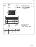
3.5.3 [3.SOUND]
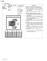
3.5.4 [4.OTHERS]
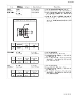
3.5.5 [7.LOW LIGHT]
3.5.6 [8.HIGH LIGHT]
No.
Setting item
Variable range
Initial setting value
RF
EXTERNAL (SV, CV)
D01
AFC GAIN
0~3
0
2
D02
H POSI
0~31
10 (/RA model) / 9 (/SA model) 10(/RA model) / 9 (/SA model)
D03
V SIZE
0~125
65
65
D04
V S CORR
0~15
3 (/RA model) / 4 (/SA model) 3 (/RA model) / 4 (/SA model)
D05
V LIN
0~15
8
8
D06
H SIZE
0~63
32
32
D07
WVMT TOP
0~3
0 (/RA model) / 1 (/SA model) 0 (/RA model) / 1 (/SA model)
D08
WVMT BTM
0~3
0
0
D09
EWCR TOP
0~31
16
16
D10
EWCR BTM
0~31
16
16
D11
EW PARA
0~63
26
26
D12
BLANK SW
0~1
0
0
No.
Setting item
Variable range
Initial setting value
A01
IN LEVEL
0~63
17
A02
FH MON
0~1
0
A03
ST VCO
0~63
36
A04
PIL CAN
0~1
0
A05
FILTER
0~63
35
A06
LOW SEP
0~63
7
A07
HI SEP
0~63
18
A08
5FH MON
0~1
0
A09
SAP VCO
0~63
37
No.
Setting item
Variable range
Initial setting value
F01
OSD POSI
0~255
22
F02
OSD PREQ
0~255
83
F03
CCD POSI
0~63
42
F04
CCD FREQ
0~255
93
F05
CCD CONT
0~63
11
F06
PUR CONT
0~255
62
F07
VNR CHK
0~255
3
F08
VCSN TM
0~255
5
F09
CCD PCHK
0~1
1
No.
Setting item
Variable range
Initial setting value
1
RED
0~255
30
2
GREEN
0~255
30
3
BLUE
0~255
30
No.
Setting item
Variable range
Initial setting value
1
RED
0~255
64
2
BLUE
0~255
64